
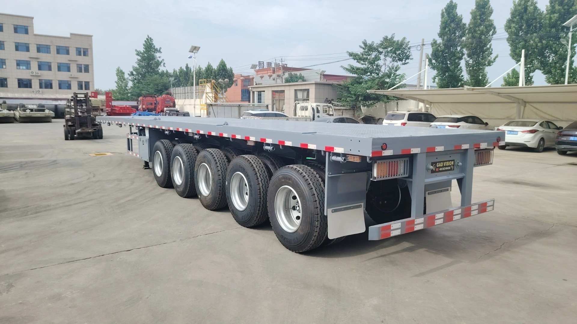
Factory view of a representative five-axle open-deck flatbed semi trailer. The photos document the finished platform, five-axle group, landing gear and rear structure; the 100-ton rating must be confirmed by the approved engineering package for the selected cargo and route.
100 Ton 5 Axle Flatbed Semi Trailer
This 100 ton 5 axle flatbed semi trailer is a project-specific open-deck configuration for heavy machinery, fabricated steel structures and dense industrial cargo with defined support points.
The five-axle group creates a longer load-reaction zone beneath the platform. For a 100-ton transport task, the cargo footprint, centre of gravity, deck structure, kingpin reaction, axle-group loads and tractor combination must be calculated together.
100-ton rating basis: The stated capacity must be supported by the approved load calculation, engineering drawing, component schedule and quotation. Final operating limits also depend on the tractor, gross combination mass, axle regulations and destination route.
Is This 100 Ton 5-Axle Flatbed Right for the Cargo?
A 100-ton transport project requires more than a long deck and five axles. The cargo support pattern, centre of gravity, point loads, kingpin reaction and axle-group loads must be calculated from the actual cargo drawing.
The tractor combination, turning envelope and permitted route must then be checked before the platform layout and running gear are approved.
Map every cargo contact point and concentrated load zone.
Position the load relative to the kingpin and five-axle group.
Check axle limits, turning space, loaded height and road clearance.
Define the Cargo Support Pattern
Provide the cargo dimensions, transport weight, centre of gravity and
every point that contacts the deck. Machinery feet, skids, frames and
other concentrated supports must be identified separately.
This information determines the required support zones and preliminary
cargo position.
Check Main-Beam and Crossmember Reactions
The support footprint must be compared with the main beams, crossmembers
and any locally reinforced deck areas. A 100-ton total cargo weight does
not describe how that weight enters the trailer structure.
Distributed loads and concentrated loads require different structural
calculations.
Review the Turning Envelope Before Production
A five-axle group creates a longer running-gear footprint. Axle spacing,
suspension behaviour, tyre scrub and the space required for tight turns
should be reviewed against loading yards, site entrances and the planned
route.
Do not assume that every five-axle layout has the same manoeuvring
characteristics.
Match the Complete Transport Combination
Confirm the tractor model, fifth-wheel height, kingpin load, tractor axle
limits and gross combination mass. The proposed route must also be
checked for axle restrictions, bridges, turning width, loaded height and
permit requirements.
The trailer, tractor and route should be approved as one transport
system.
Send the cargo drawing, transport weight, centre of gravity, support locations, loading method, tractor data and destination route. CHENLU will use these inputs to review the platform load path, kingpin reaction, five-axle distribution and required running-gear configuration.
What Defines the Final 100 Ton Five-Axle Flatbed Specification?
The reference drawing establishes the trailer envelope and five-axle
arrangement. For a 100-ton project, the final structure must then be
developed from the cargo weight, centre of gravity, support footprint,
tractor data and operating route.
These inputs determine the deck structure, kingpin reaction,
axle-group loads, running gear, braking package and cargo-securing
arrangement.
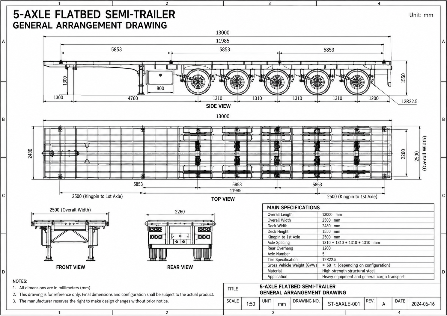
The supplied drawing identifies a 13,000 mm overall-length reference,
a 2,500 mm maximum external width, five axle positions and a 12R22.5
tyre notation.
These values define the reference envelope. They do not by themselves
confirm a 100-ton payload, final component ratings or permission to
operate on a specific route.
What Information Is Required for the 100-Ton Load Review?
A five-axle layout must be configured from the actual load path—not from the target payload alone. Submit the following information so the deck, tractor reaction, axle group and route limits can be reviewed as one transport system.
Operating Weight and Centre of Gravity
Provide the cargo operating weight, overall dimensions, centre of gravity and required transport orientation. Identify removable components and any difference between shipping and operating weight.
Contact Points and Concentrated Loads
Mark every skid, foot, wheel, cradle or frame section that transfers weight to the deck. Include the size, position and reaction at each contact point where available.
Loading Method and Required Clearance
Confirm whether the cargo will be handled by crane, forklift, ramp or another approved method. Define side access, overhead clearance, deck-edge access and the required loading sequence.
Kingpin Load and Coupling Geometry
Provide the tractor model, fifth-wheel height, tractor axle limits and relevant chassis dimensions. These inputs are needed to calculate kingpin reaction, coupling attitude and cab clearance.
Five-Axle Reactions and Turning Envelope
Calculate the load transferred across the complete five-axle group. Review axle spacing, suspension response, tyre ratings, rear overhang, turning space and tyre scrub for the intended operating area.
Road Limits and Required Equipment
Confirm the destination country, port, operating route, road conditions, bridge or axle restrictions and required electrical, braking, lighting and marking specifications.
How the Five-Axle Flatbed Moves from Load Data to Production
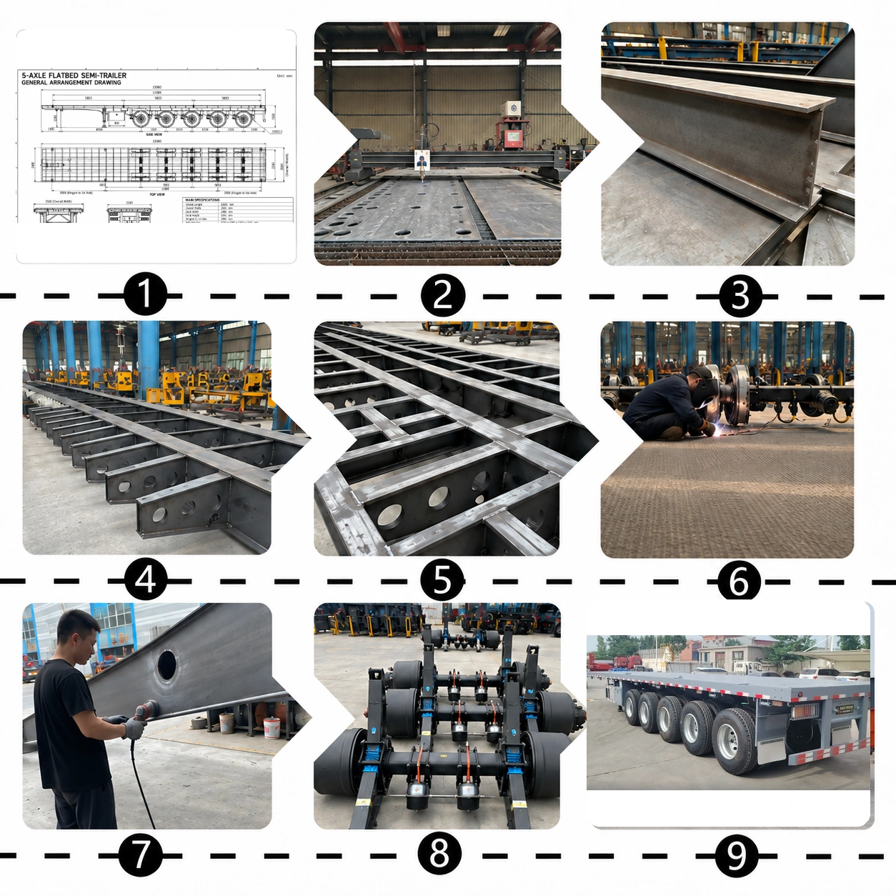
Production should begin only after the cargo inputs, load calculation, engineering drawing and component schedule describe the same configuration. The factory-process image documents the general manufacturing sequence; final capacity and market requirements must be confirmed in the approved project documents.
Confirm the Design Basis Approve the cargo weight, centre of gravity, support footprint, tractor and operating route.
Complete the Load Review Calculate the deck reactions, kingpin load, axle-group distribution and required structural support.
Release Production Documents Issue the approved frame, deck and running-gear drawings together with the material and component schedules.
Assemble and Inspect Check the principal dimensions, running gear, brakes, electrical equipment, cargo-securing provisions and required documentation.
13 m 5 Axle Flatbed Trailer Drawing and Key Dimensions
Use this general arrangement drawing to review the platform dimensions, coupling area, five-axle layout and available cargo space. Payload, component ratings and cargo-restraint equipment are specified for the actual cargo and destination route.
What Should Be Matched to the Flatbed Drawing?
The drawing provides the trailer envelope. Cargo position, tractor connection, loading method and route conditions are added when the order configuration is prepared.
Compare cargo length, width and height with the available platform and loaded transport envelope.
Provide the transport weight and centre of gravity used to determine the planned deck position.
Mark every skid, foot, wheel or frame that transfers cargo weight into the flatbed platform.
Match the kingpin position, fifth-wheel height and front clearance to the intended tractor.
State whether the cargo will be placed by crane, forklift, dock or another approved loading system.
Identify the required tie-down locations, loading directions, blocking points and special fixtures.
Review the landing gear, toolbox, suspension and equipment installed beneath the platform.
Check road width, turning space, height restrictions, axle limits and delivery-site access.
Optional Parts And Accessories
Semi-Trailer Axle Support Plate
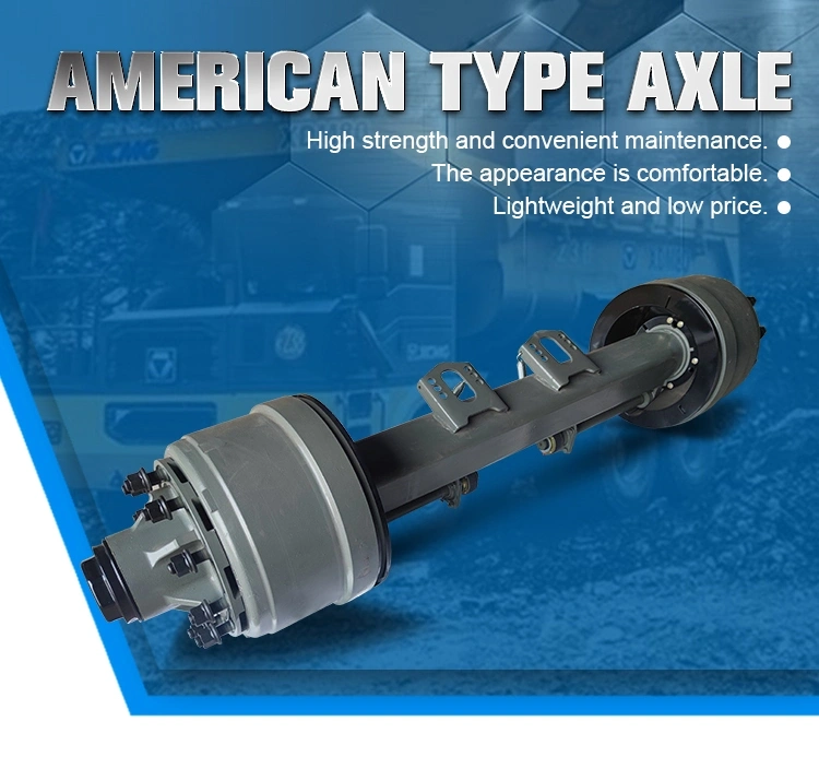
American-Style Axle
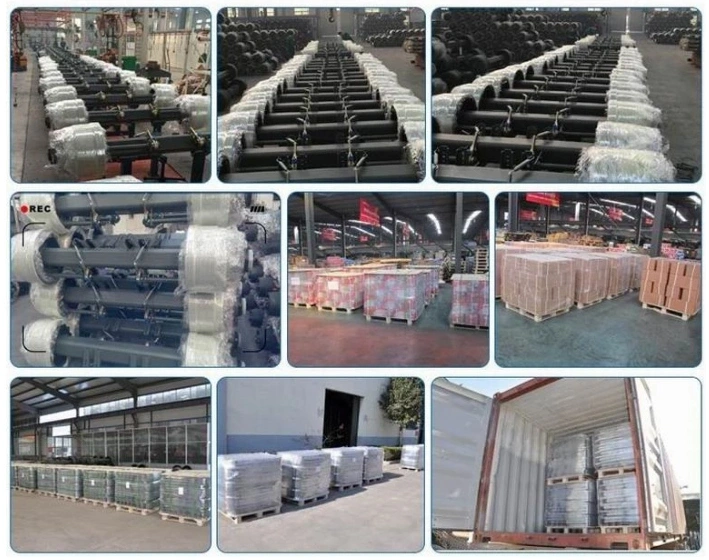
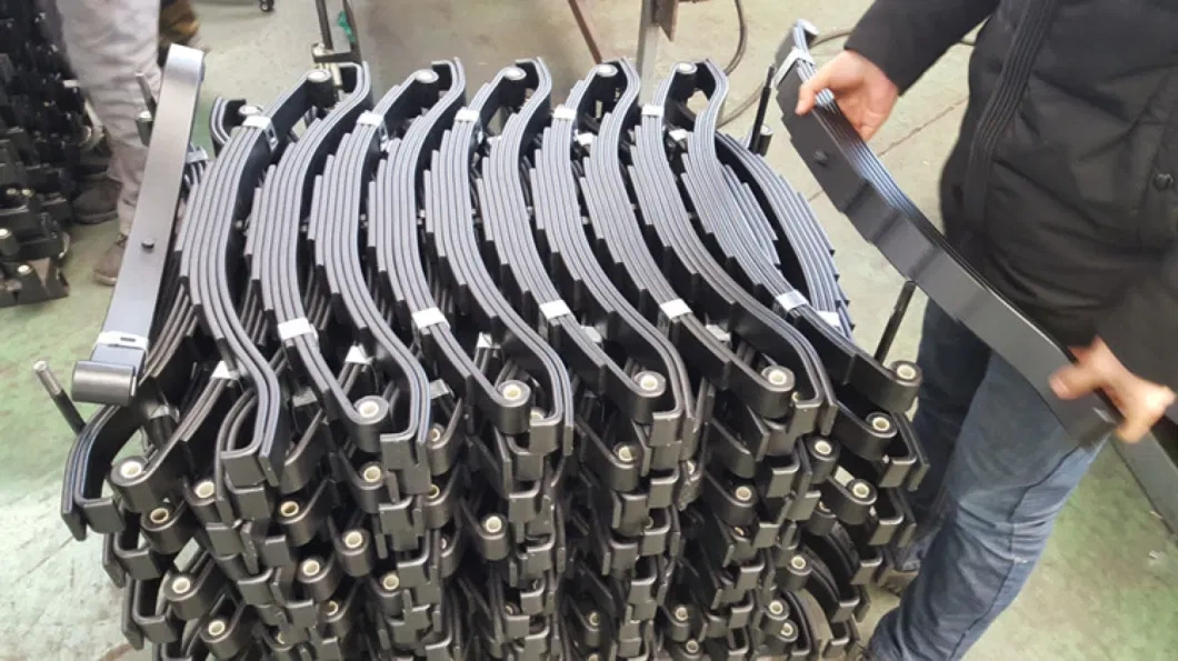
Trailer Suspension Parts
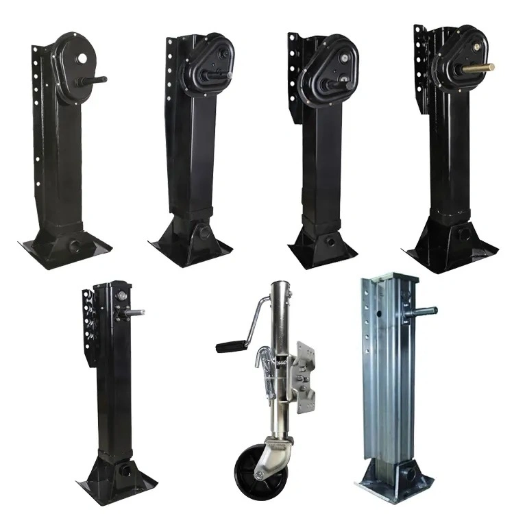
Trailer Suspension Support Leg
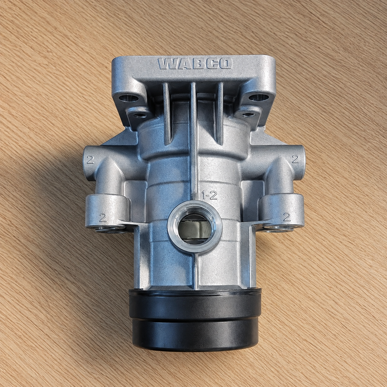
WABCO Brake Valve
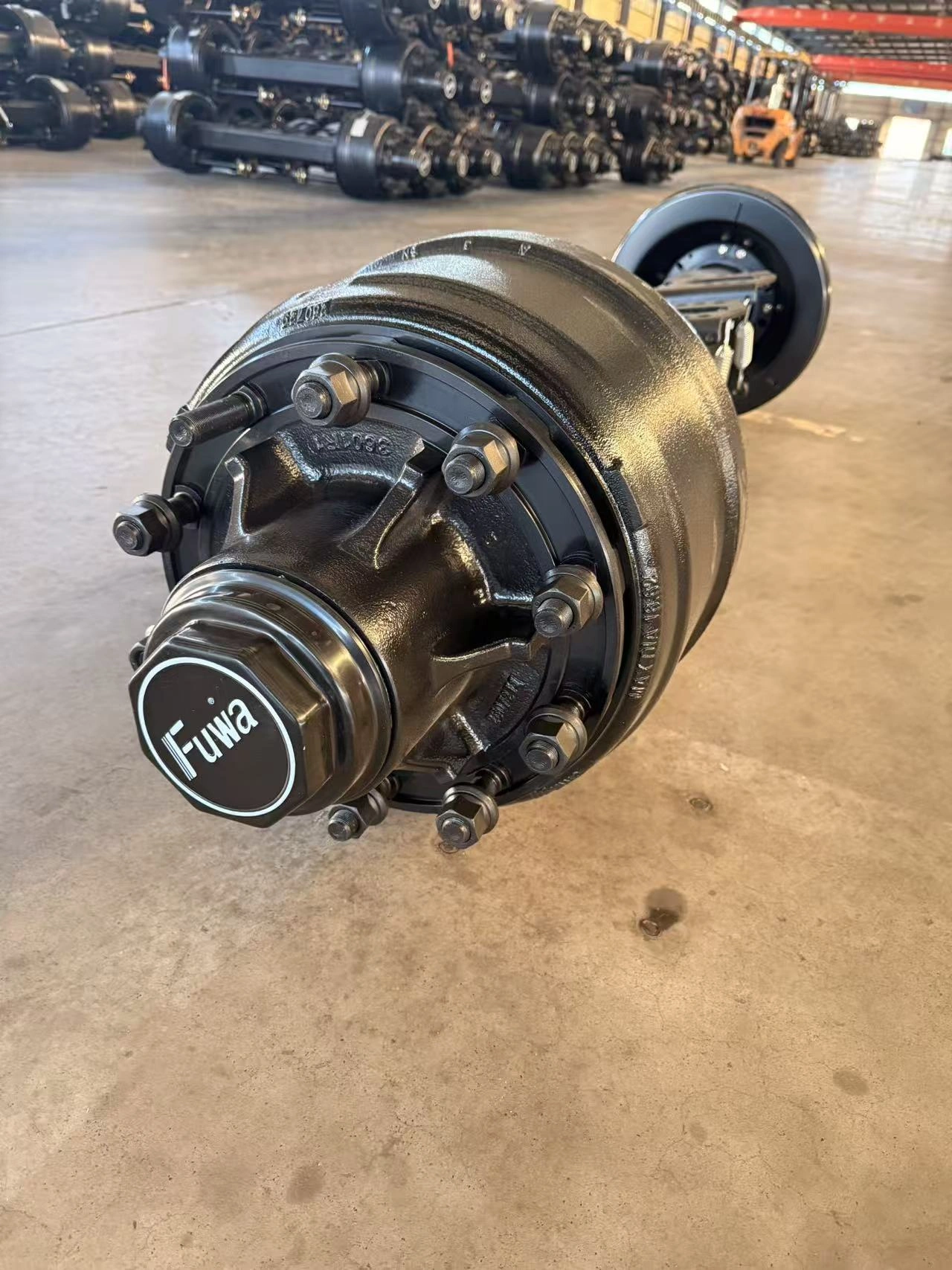
FUHUA (TUWA) Trailer Axle
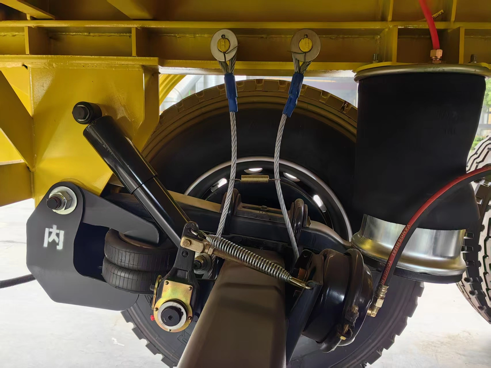
German-Style Trailer Suspension
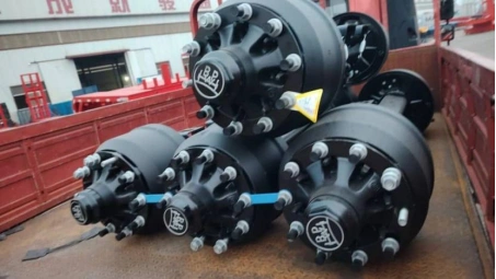
BPW Trailer Axle
Why Trust Chenlu?
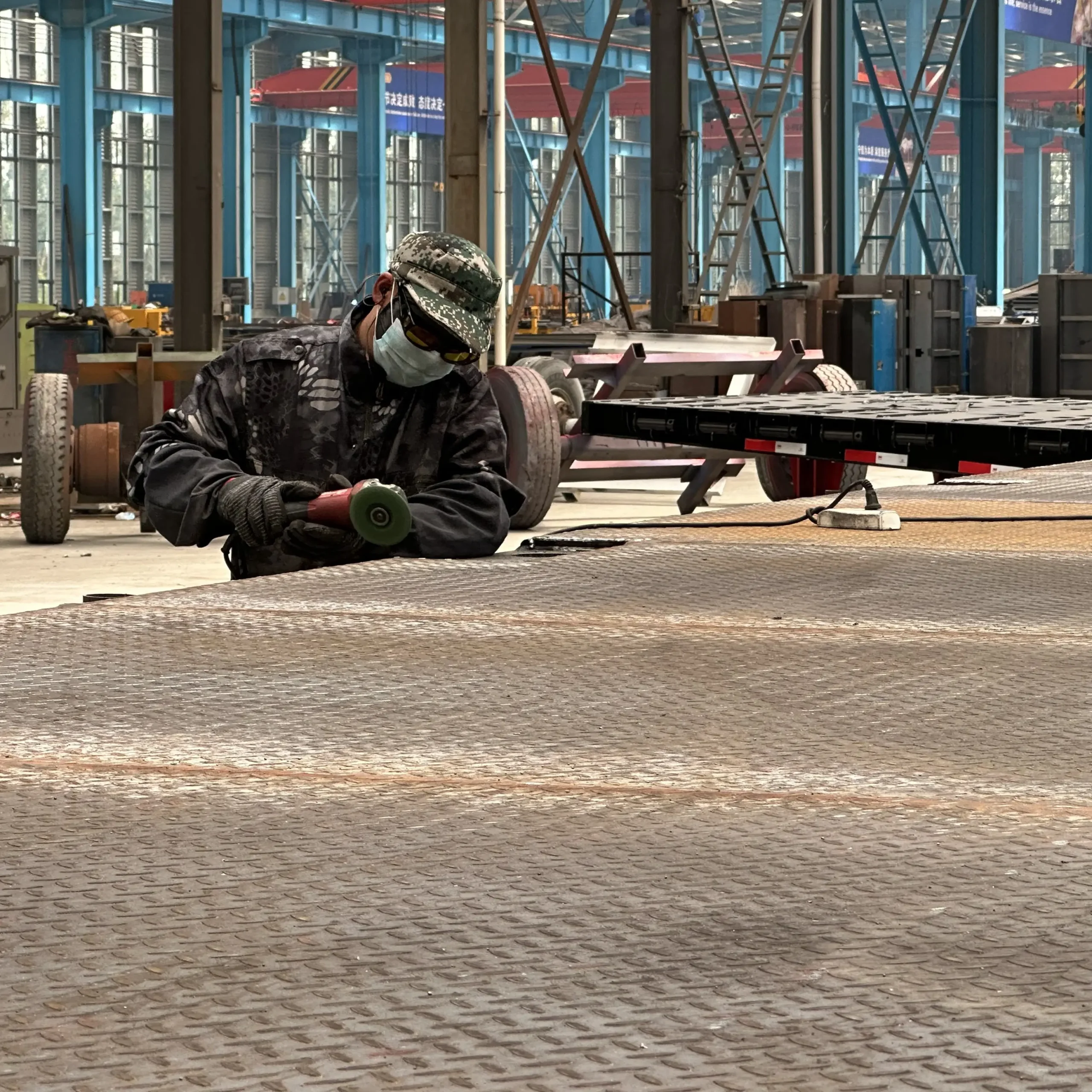
Factory-Direct Manufacturing
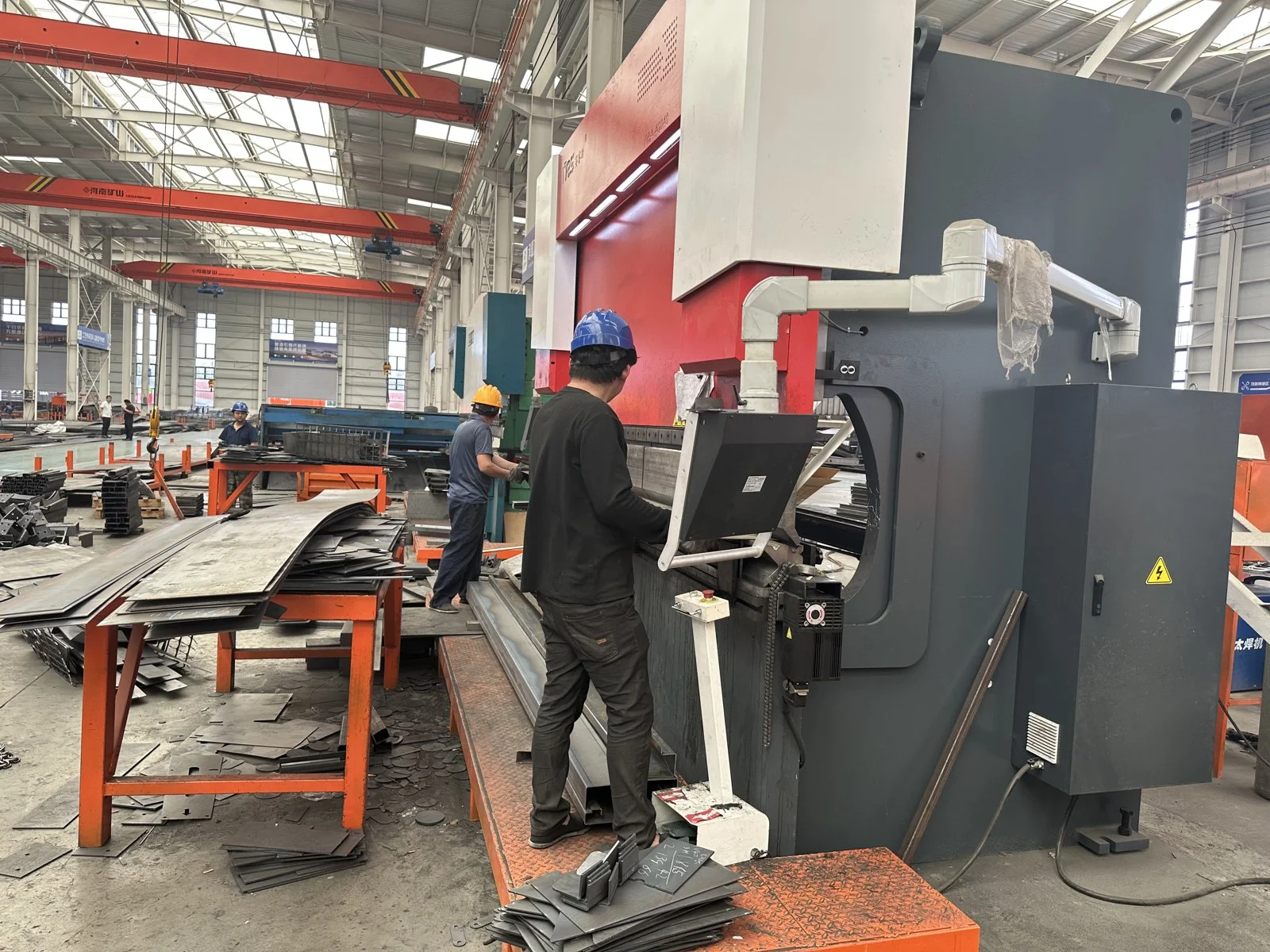
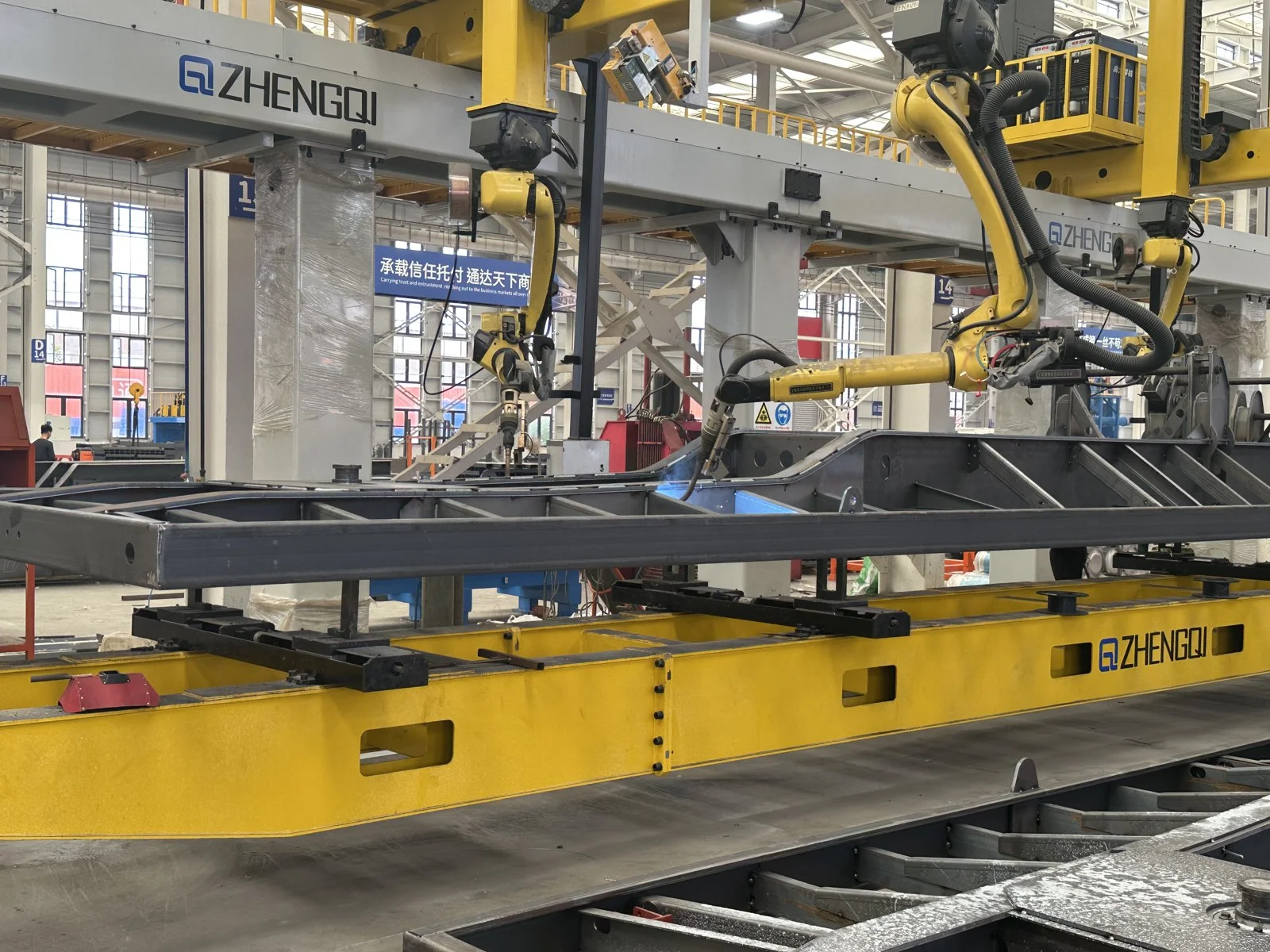
CHENLU presents its own semi-trailer manufacturing base with modern workshops, CNC cutting, automatic welding lines and painting facilities. This supports direct communication between the buyer, engineering team and production team.
OEM/ODM Configuration Review
The published customization scope includes axle number and load configuration, suspension type, ride height, frame reinforcement, deck requirements, branding, colour and logo. The final scope should be confirmed against the cargo, tractor and destination route.
Process-Based Quality Control
The factory workflow covers material preparation, main-beam welding, frame assembly, surface treatment, painting, final assembly, inspection and testing. Quality checks should be recorded against the actual project configuration before delivery.

B2B Export and Project Support
CHENLU works with fleet owners, contractors, distributors and project buyers across logistics, construction, mining and heavy-equipment transport applications. The quotation should confirm the tractor interface, route, axle-load requirements and local permits.
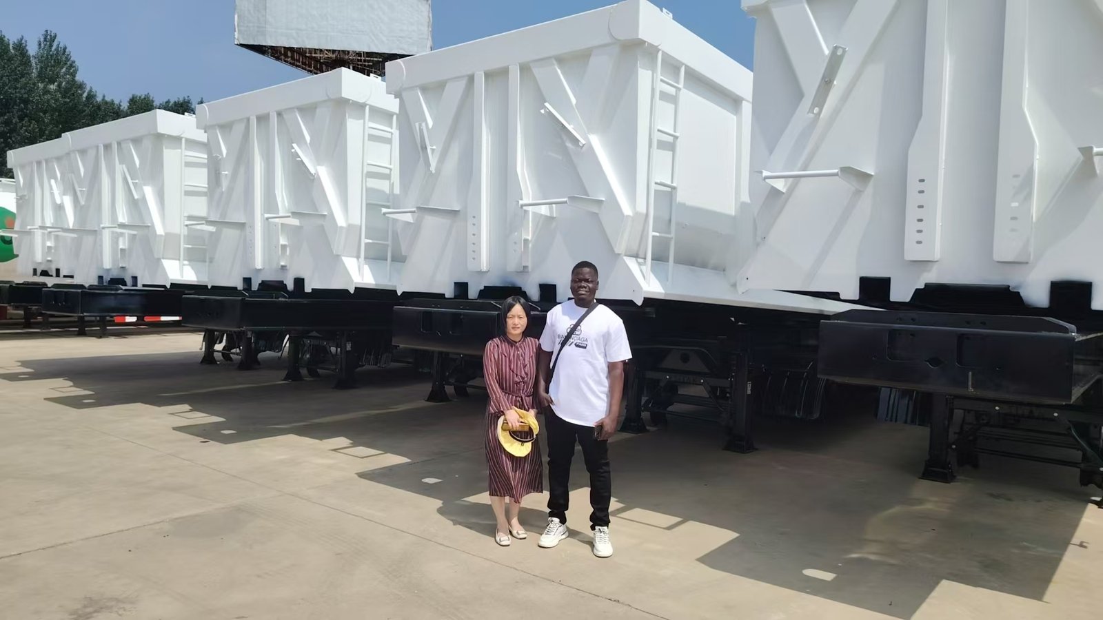
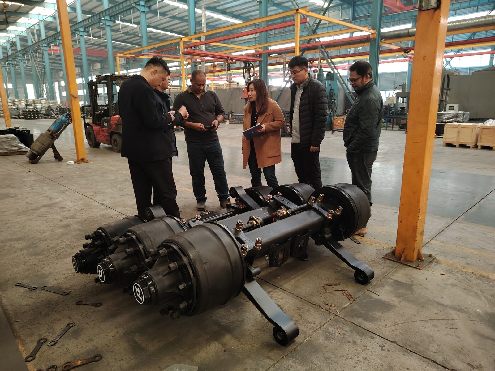
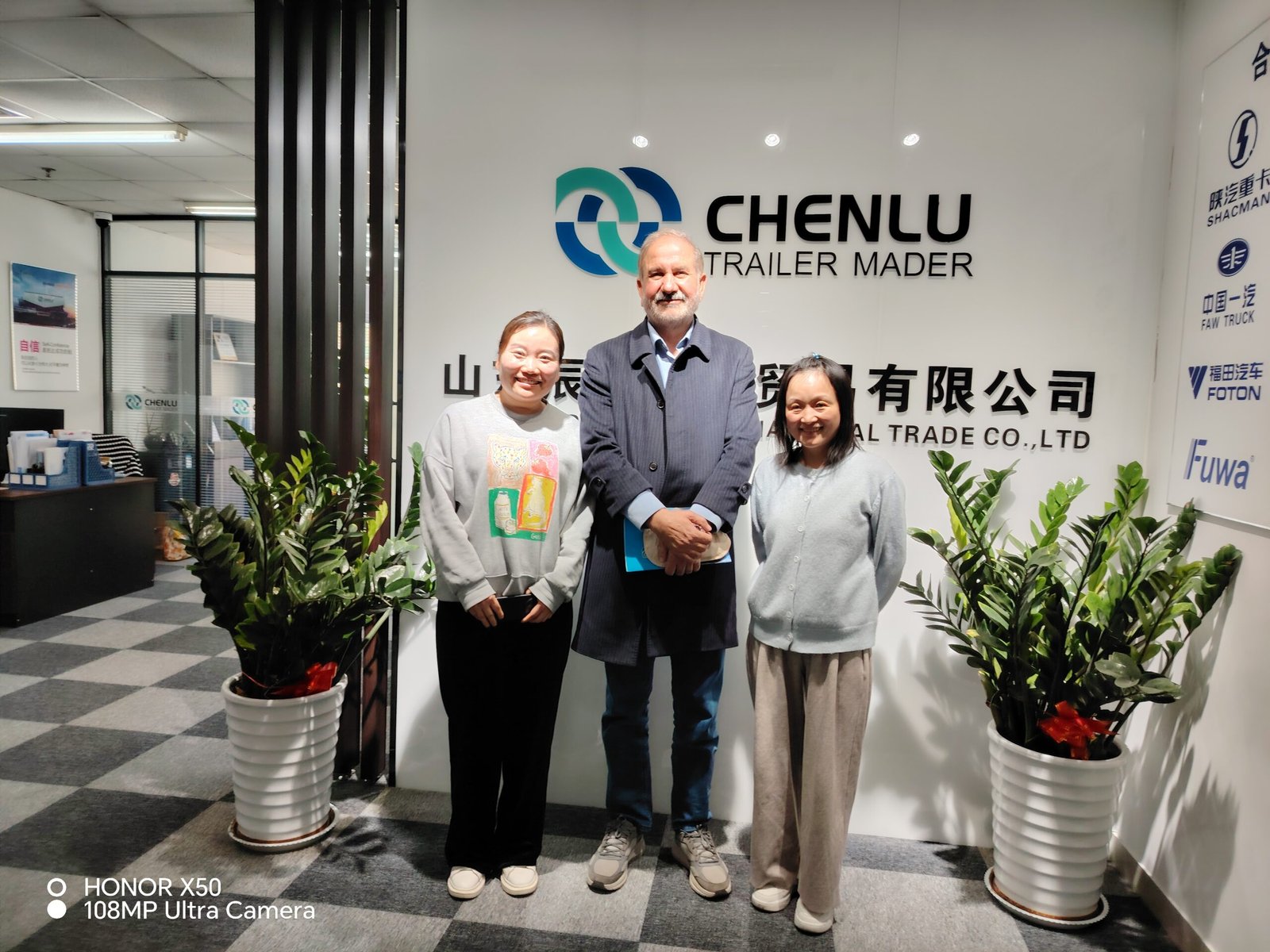
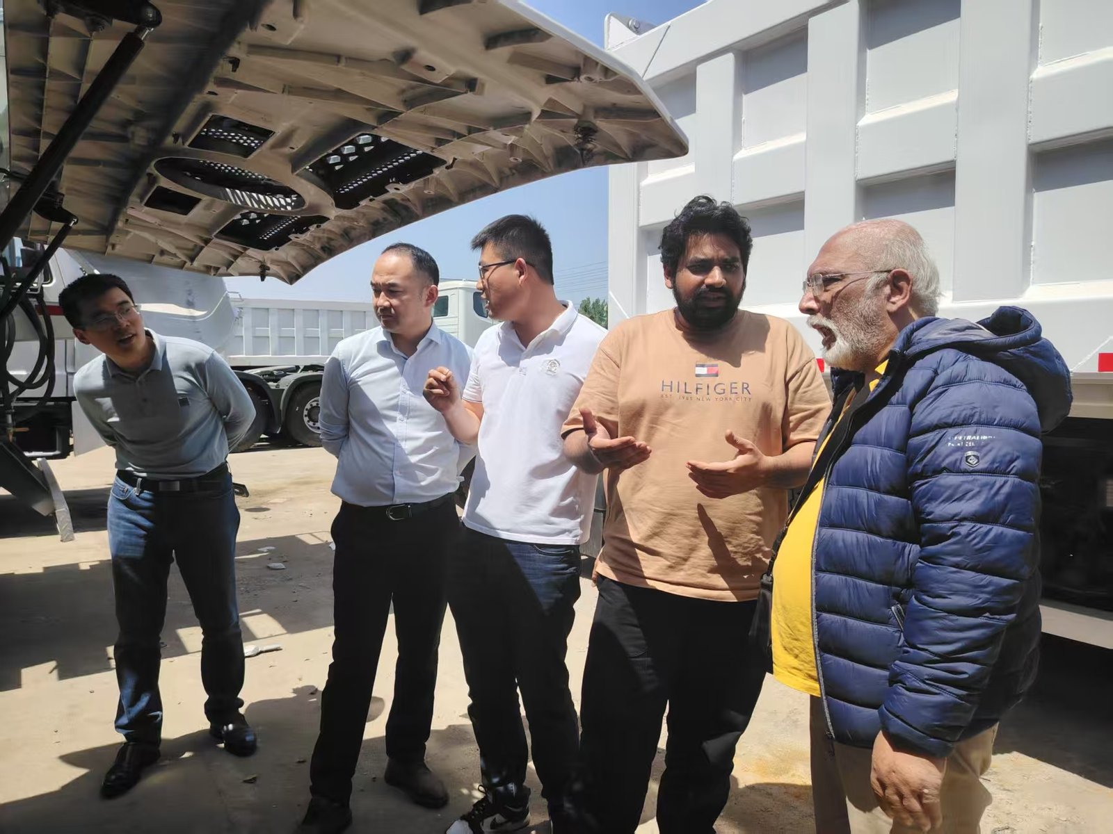
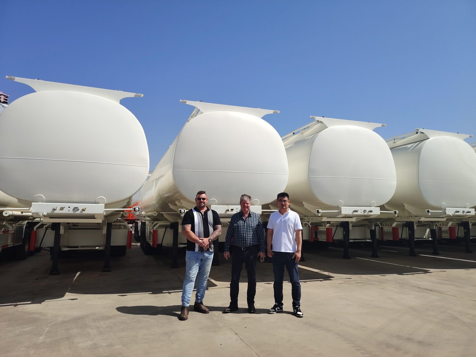
Meet Chenlu and Review the Manufacturing Process
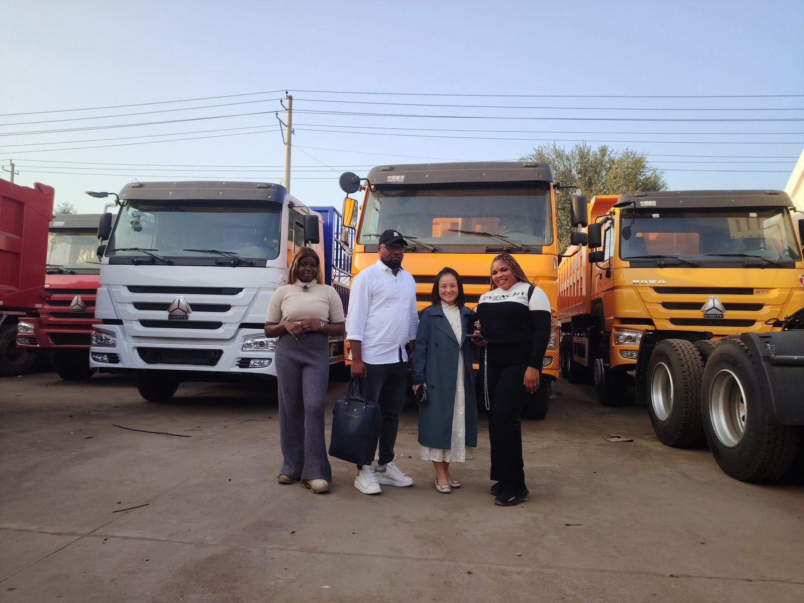
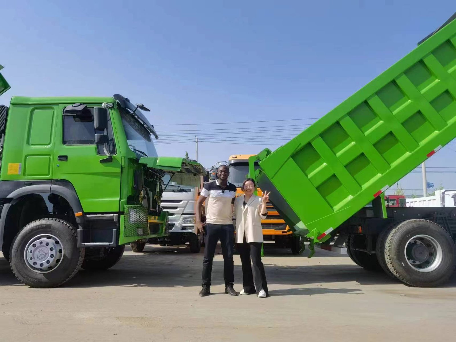
Customer visits support direct communication between buyers, engineering teams and the manufacturing department before the final configuration is confirmed.

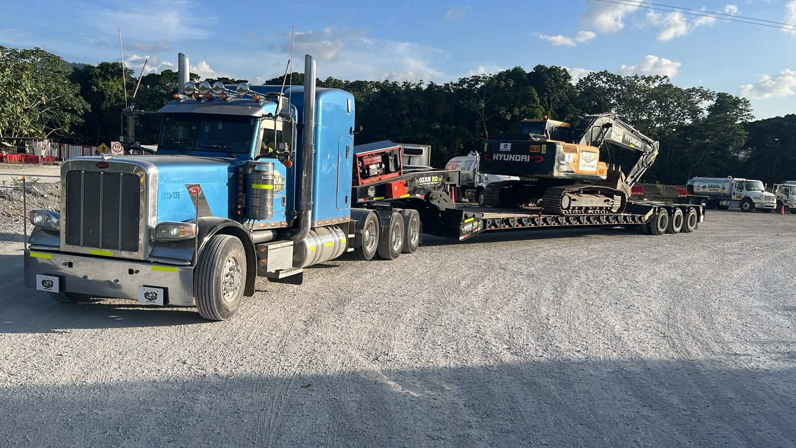
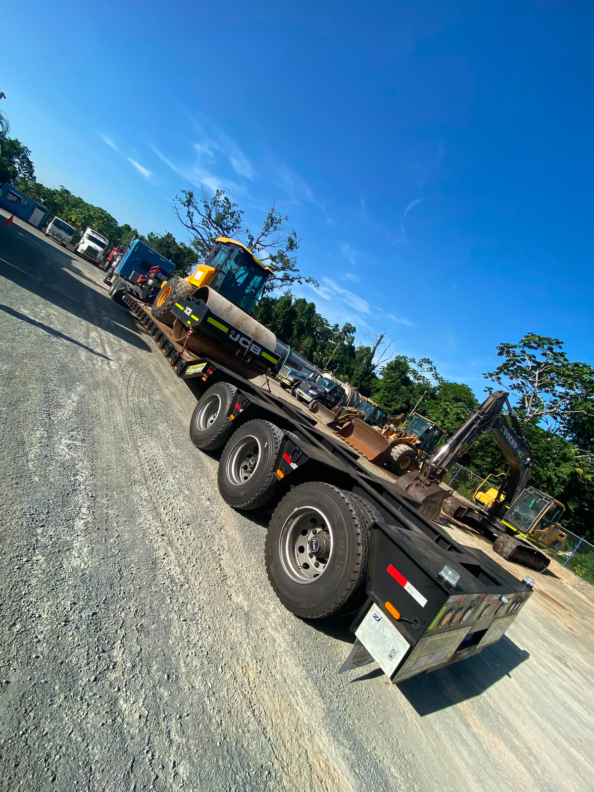
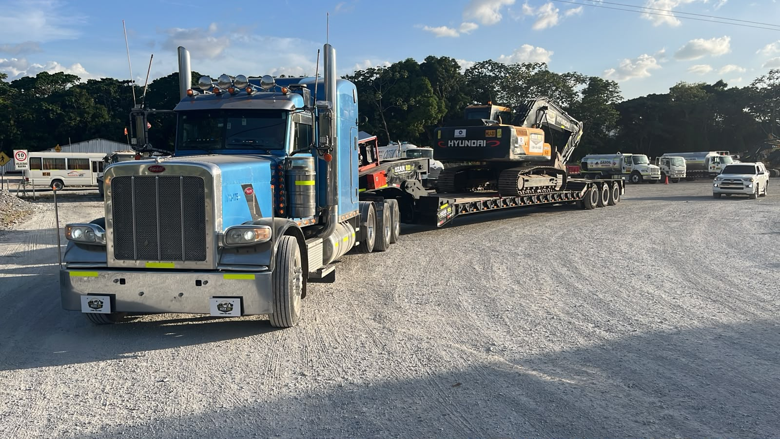
Follow the Project from Delivery to Customer Feedback
Use approved delivery photos, project records and customer comments to present the completed communication and delivery process.

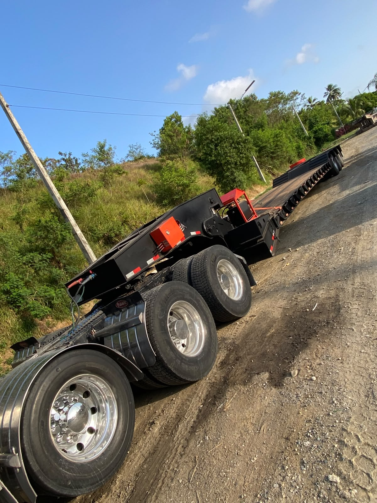
Publish the Original Customer Message with Permission
Add an approved customer comment, delivery record or project feedback here after the customer confirms the wording and image usage.
Approved delivery photo or project record.
Original customer message with permission.
Approved feedback about communication and support.
Related Products
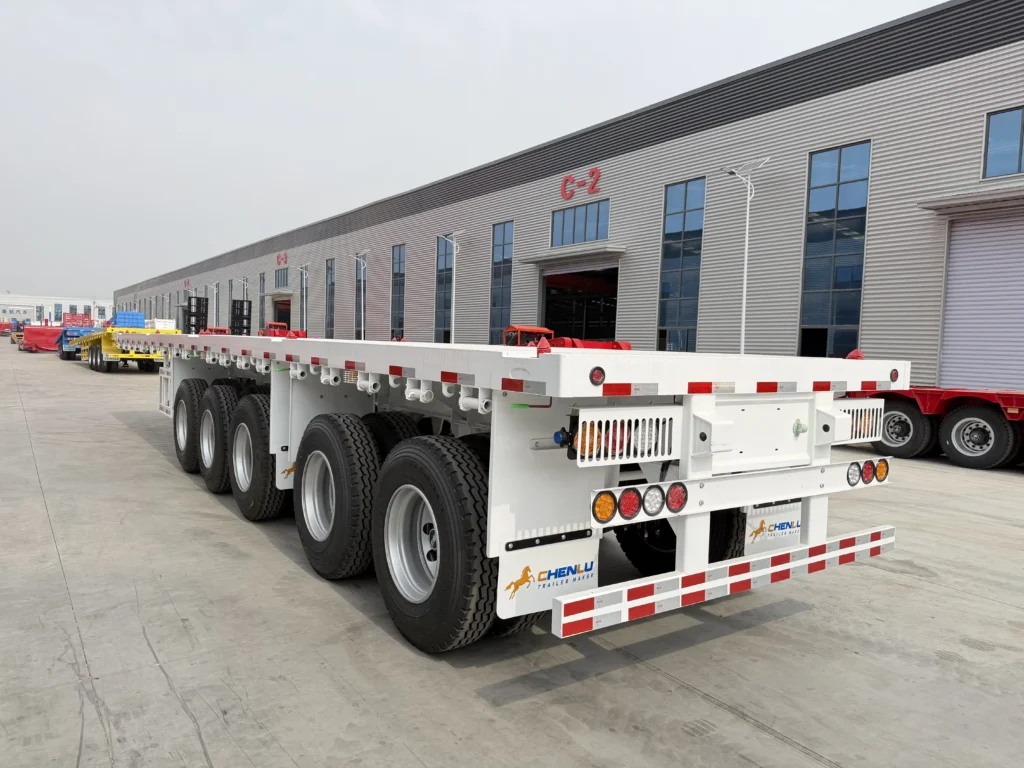
Flatbed Semi Trailer
100 Ton 5 Axle Flatbed Semi Trailer with Mechanical Suspension
View Product ↗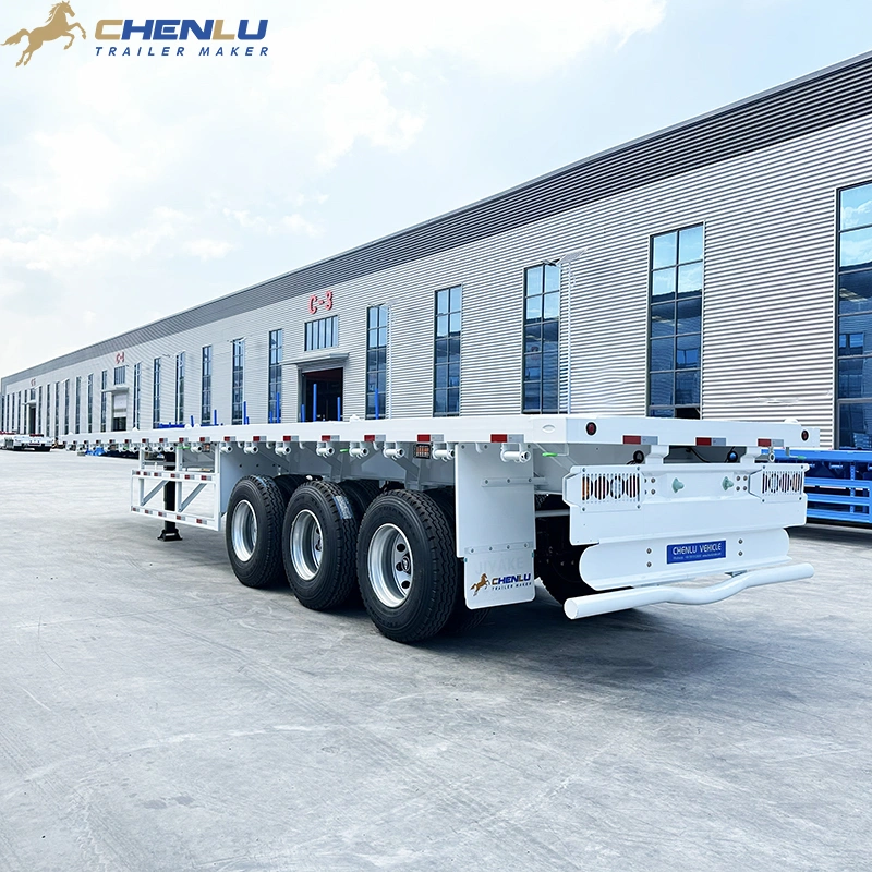
Flatbed Semi Trailer
12.5 m 3 Axle Flatbed Semi Trailer | CHENLU
View Product ↗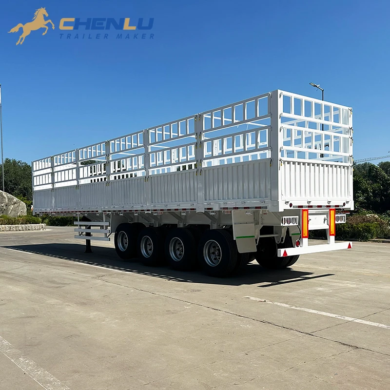
Fence Cargo Trailer
12.5 m 4 Axle Fence Cargo Semi Trailer for Tanzania
View Product ↗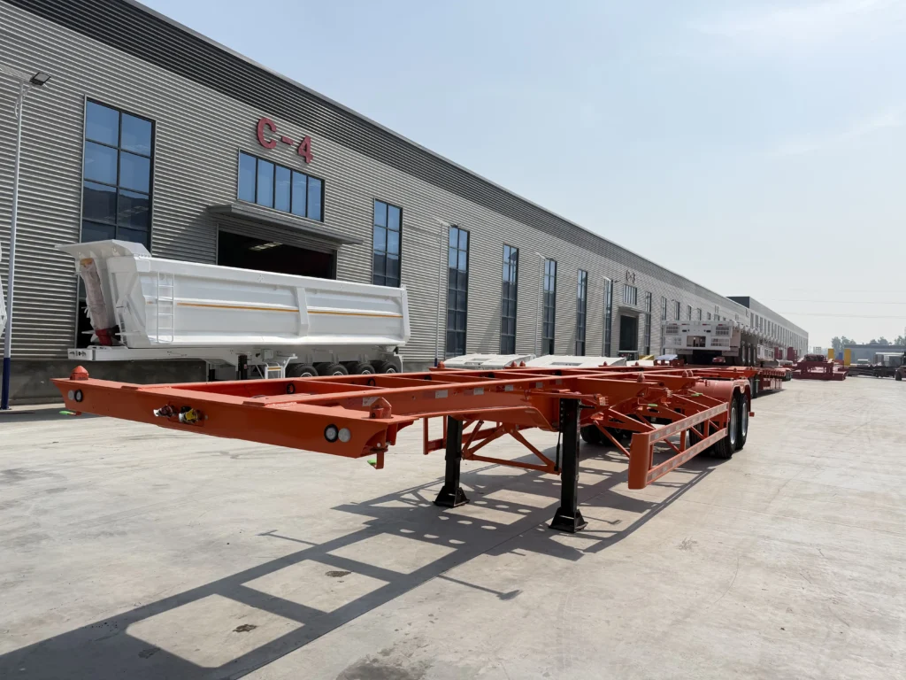
Container Chassis / Skeleton Trailer
12.5m 2 Axle 40ft Skeleton Semi Trailer
View Product ↗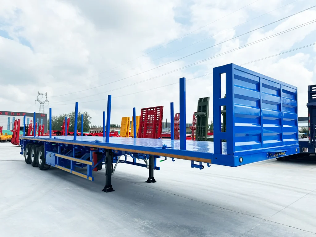
Flatbed Semi Trailer
13.6m 3 Axle Flatbed Semi Trailer with Stakes for Saudi Arabia
View Product ↗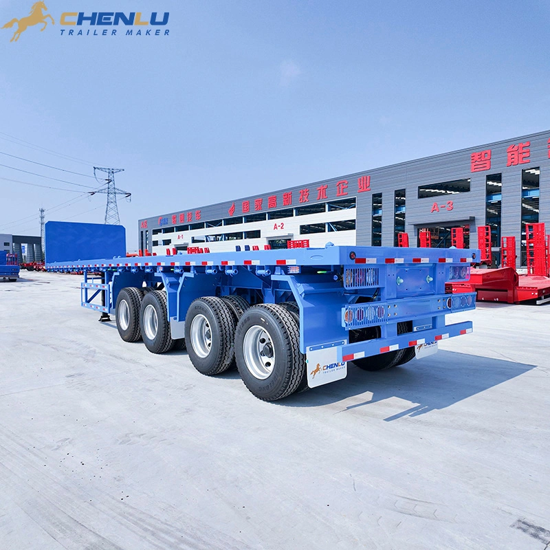
Flatbed Semi Trailer