
BULK CEMENT TRANSPORT · FOUR AXLES
65 m³ 4-Axle Cement Tanker Trailer
The CHENLU 65 m³ cement tanker trailer carries bulk cement, fly ash and mineral powder. It has a single-compartment tank, four rear axles and a front-mounted engine and air compressor.
The engine drives the compressor for pneumatic unloading. Material leaves through the discharge pipe and hose connected to the receiving silo.
FOR A QUOTE
Send your material, destination and order quantity. Include the silo inlet size and hose length if available.
- Tank volume
- 65 m³
- Rear axle group
- 4 Axles
- Tank layout
- Single Compartment
- Unloading method
- Pneumatic
4-Axle Cement Tanker Trailer Features
The 65 m³ bulk cement trailer is loaded through the tank-top openings and unloaded through a hose connected to the receiving silo. A front-mounted engine drives the air compressor for pneumatic unloading.
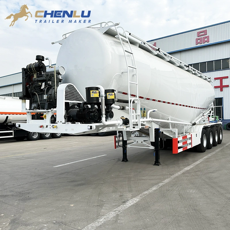
Front-Mounted Engine and Air Compressor
The engine and air compressor sit side by side on the front platform. The trailer carries its own compressor drive, so pneumatic unloading does not rely on the tractor's power take-off.
The engine supplies power; the compressor supplies the air used to discharge the material. Both units are mounted outside the tank body for inspection and servicing.
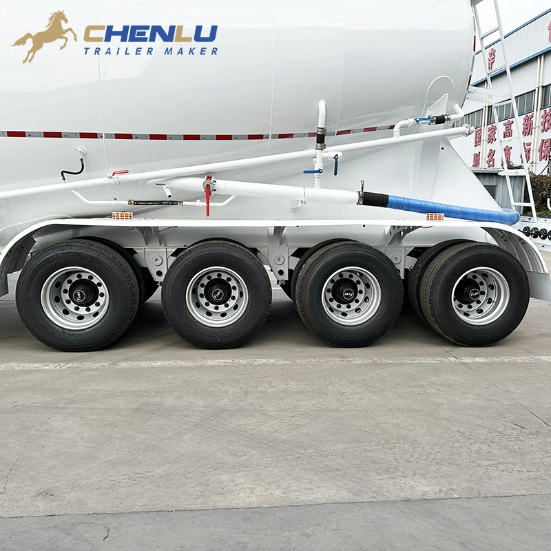
Side Discharge Pipe and Hand Valves
Air lines, the discharge pipe and hand-operated valves run along the lower side of the tank. The discharge outlet connects to a hose for transferring cement or fly ash into the receiving silo.
Compressed air carries the material through the discharge line, rather than unloading it by tipping the tank. The hose coupling needs to match the silo inlet.
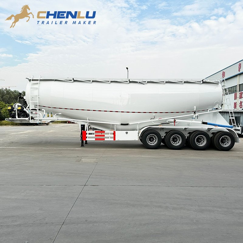
Four-Axle Rear Layout
Four axles are grouped beneath the rear of this 65 m³ cement bulker trailer, with mudguards over the wheels. The sloping-bottom tank sits above the chassis.
The rear axle group supports the tank chassis, while the tractor carries the load at the front coupling. Side guards and landing legs are fitted ahead of the rear wheels.
Cement Tanker Trailer Production Process
Typical fabrication and assembly stages for a 65 m³ four-axle cement tanker trailer. Tank and chassis work can run in parallel before final assembly.
-
Drawing and Plate Preparation
Confirm the 65 m³ tank shape, four-axle chassis and equipment positions. Cut the tank plates, frame sections and mounting parts to the drawing.
-
Tank Forming and Welding
Form the shell, end sections and sloping lower tank sections. Position and weld the parts, then add the loading openings and discharge fittings.
-
Tank and Chassis Assembly
Assemble the frame and tank supports. Position the tank, suspension mounts and landing legs. Prepare the front platform for the engine and compressor.
-
Surface Preparation and Painting
Prepare the tank and chassis exterior for coating, then apply the specified finish. The pictured configuration has a white exterior.
-
Four Axles and Discharge Equipment
Install the four-axle running gear, front-mounted engine and air compressor. Connect the air lines, hand valves, discharge pipes and hose fittings.
-
Final Assembly Review
Complete the remaining fittings. Review the running gear, front power unit, pipe connections, lights and exterior parts against the build specification.
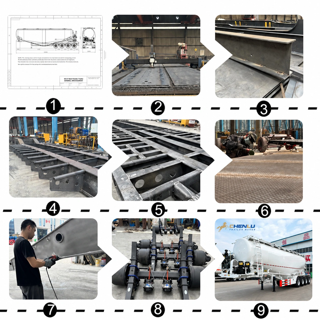
Reference production stages covering material preparation, chassis fabrication, structural welding, surface work and final running-gear assembly.
65 m³ 4-Axle Cement Tanker Trailer Drawing
Side and rear views show overall length, width, height and four-axle spacing. Use these dimensions to check tractor and site access.
The reference drawing places the power equipment at a different end from the finished trailer photos. Confirm the front-mounted engine and compressor layout on the order drawing.
Tractor, Loading Point and Silo Connections
Send the tractor details and silo inlet dimensions alongside the cargo type and required load.
State whether you carry cement, fly ash or mineral powder, including its bulk density.
Provide the cargo weight you plan to carry for the load-distribution review.
Send the tractor model, fifth-wheel height and coupling details.
The photos show a front-mounted engine and compressor. Confirm this position on the order drawing.
Provide the receiving silo’s inlet connection size and height.
State the hose length and layout between the trailer and receiving silo.
Check the headroom available above the top loading hatches and walkway.
Provide the destination country and any known height, turning-space or axle-load restrictions.
Optional Parts And Accessories
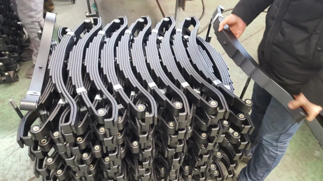
Semi-Trailer Axle Support Plate
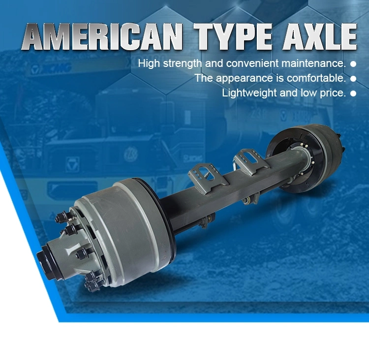
American-Style Axle
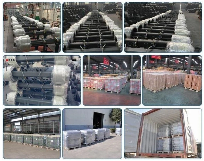
Trailer Suspension Parts
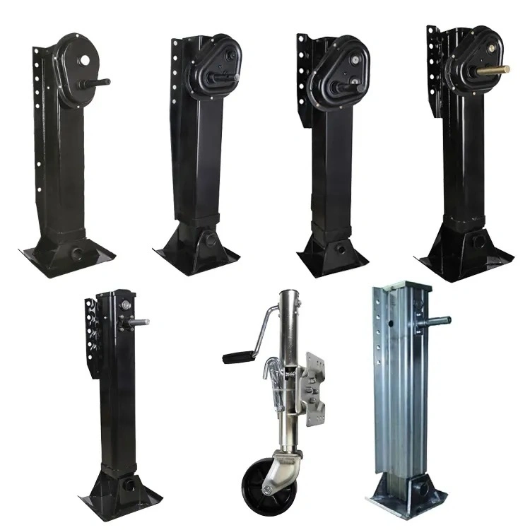
Trailer Suspension Support Leg
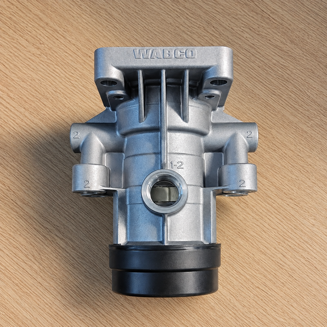
WABCO Brake Valve
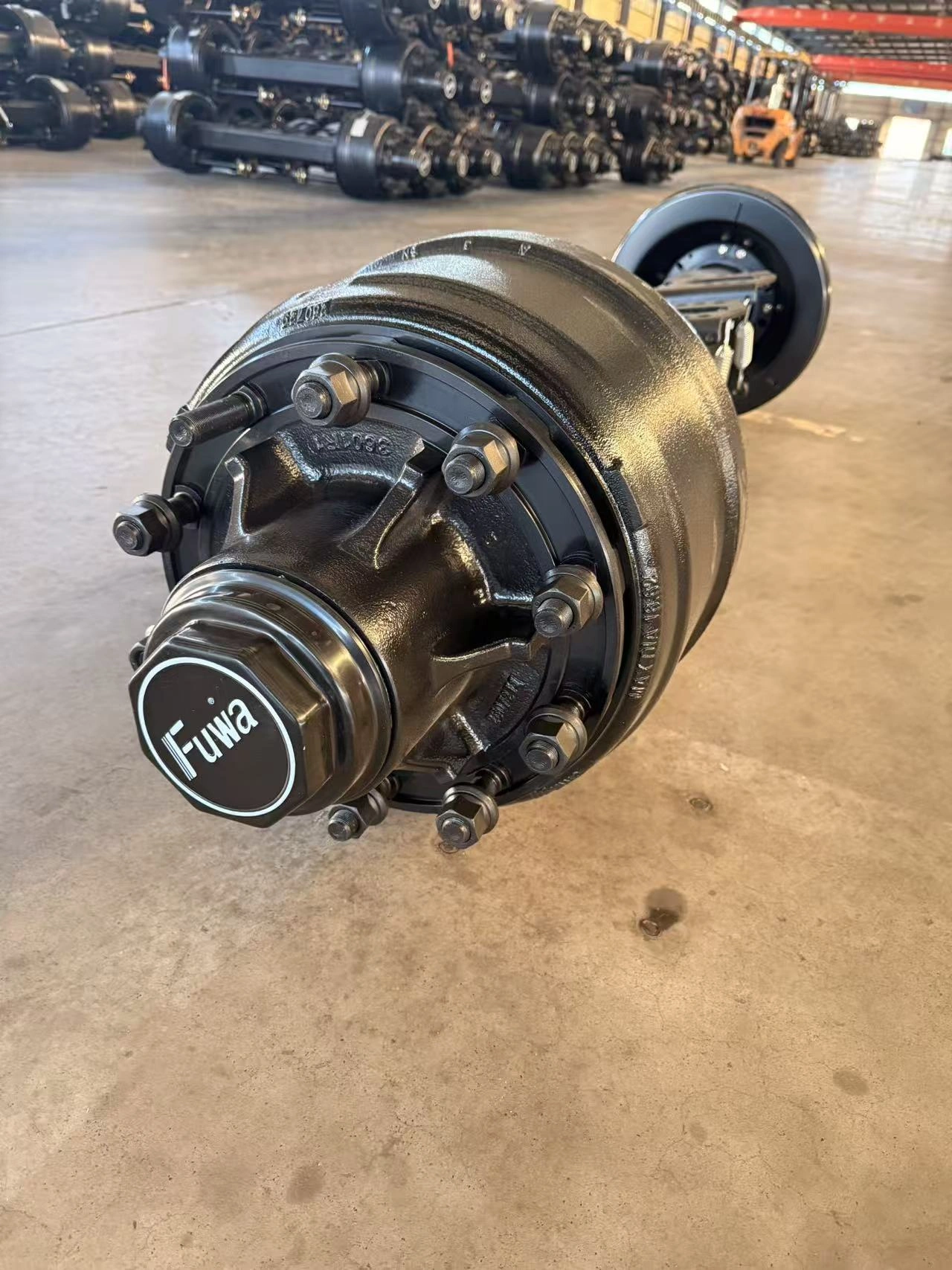
FUHUA (TUWA) Trailer Axle
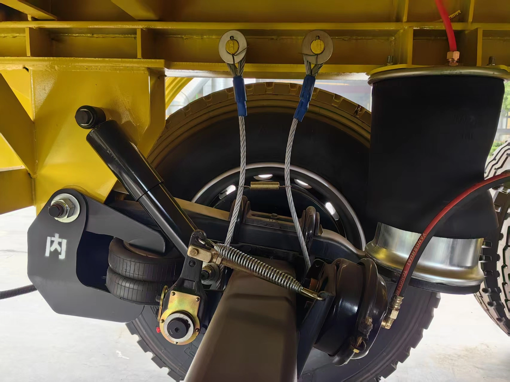
German-Style Trailer Suspension
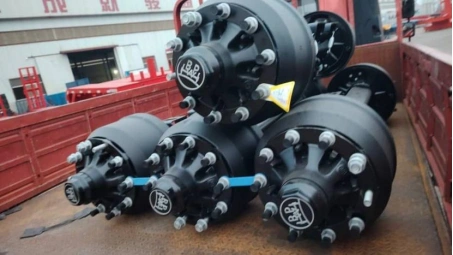
BPW Trailer Axle
Why Trust Chenlu?
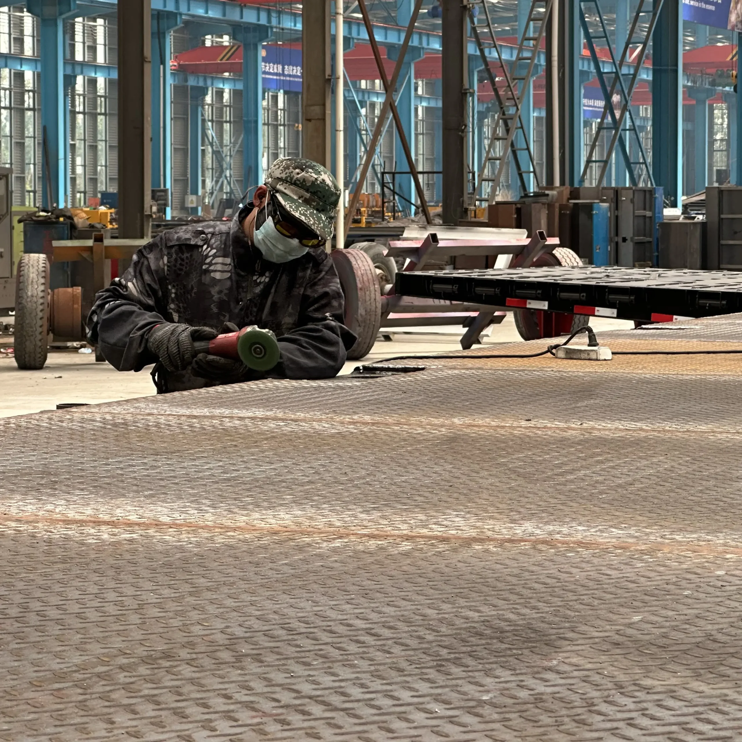
Factory-Direct Manufacturing
CHENLU presents its own semi-trailer manufacturing base with modern workshops, CNC cutting, automatic welding lines and painting facilities. This supports direct communication between the buyer, engineering team and production team.
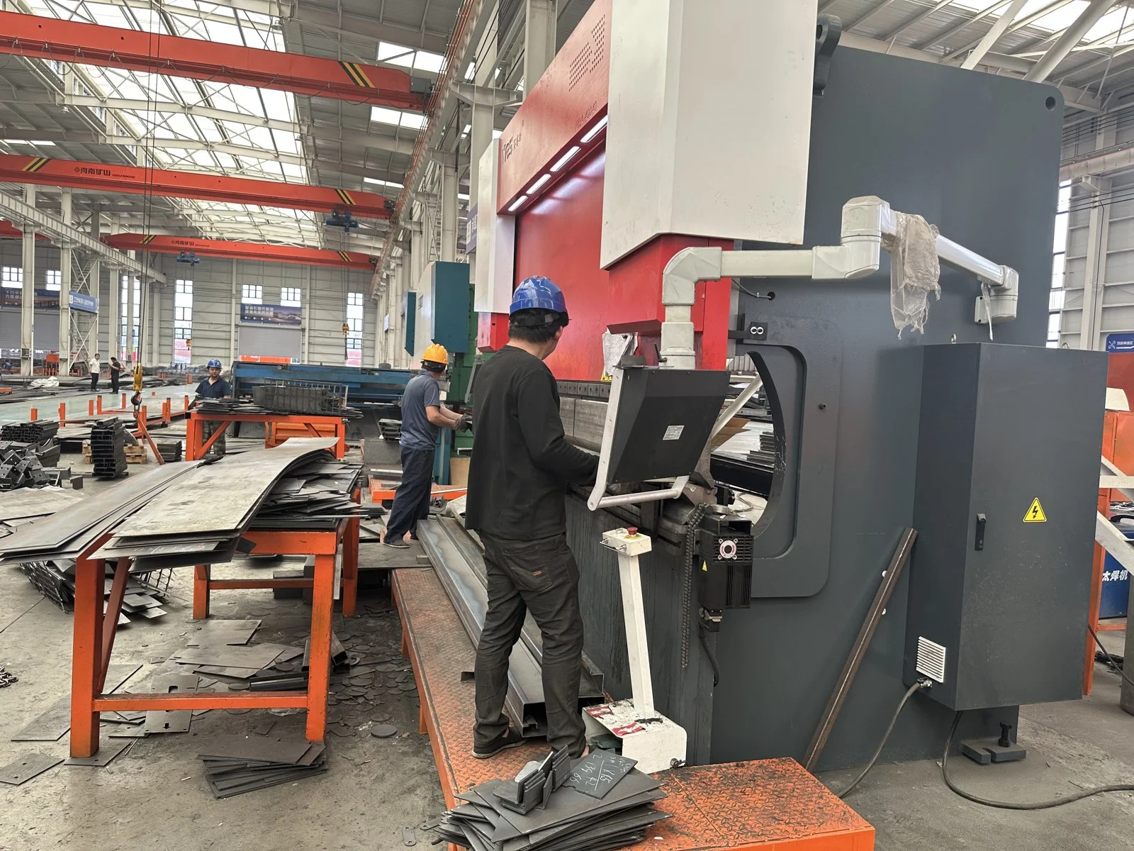
OEM/ODM Configuration Review
The published customization scope includes axle number and load configuration, suspension type, ride height, frame reinforcement, deck requirements, branding, colour and logo. The final scope should be confirmed against the cargo, tractor and destination route.
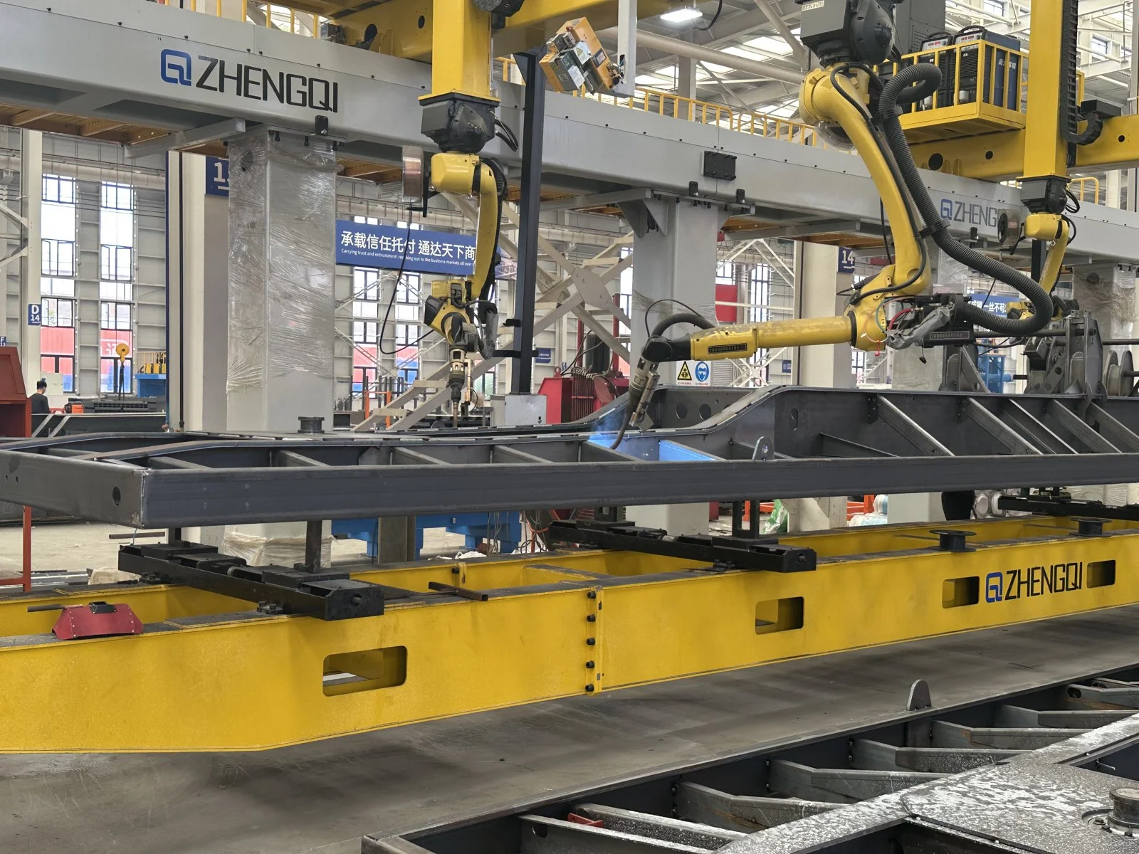
Process-Based Quality Control
The factory workflow covers material preparation, main-beam welding, frame assembly, surface treatment, painting, final assembly, inspection and testing. Quality checks should be recorded against the actual project configuration before delivery.

B2B Export and Project Support
CHENLU works with fleet owners, contractors, distributors and project buyers across logistics, construction, mining and heavy-equipment transport applications. The quotation should confirm the tractor interface, route, axle-load requirements and local permits.
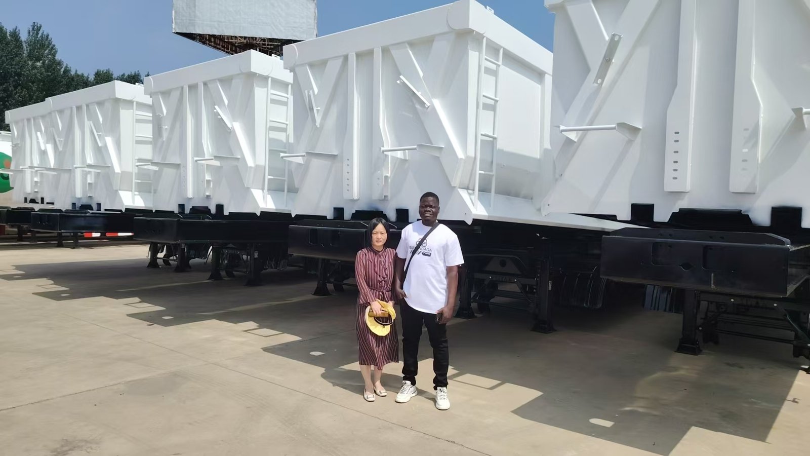
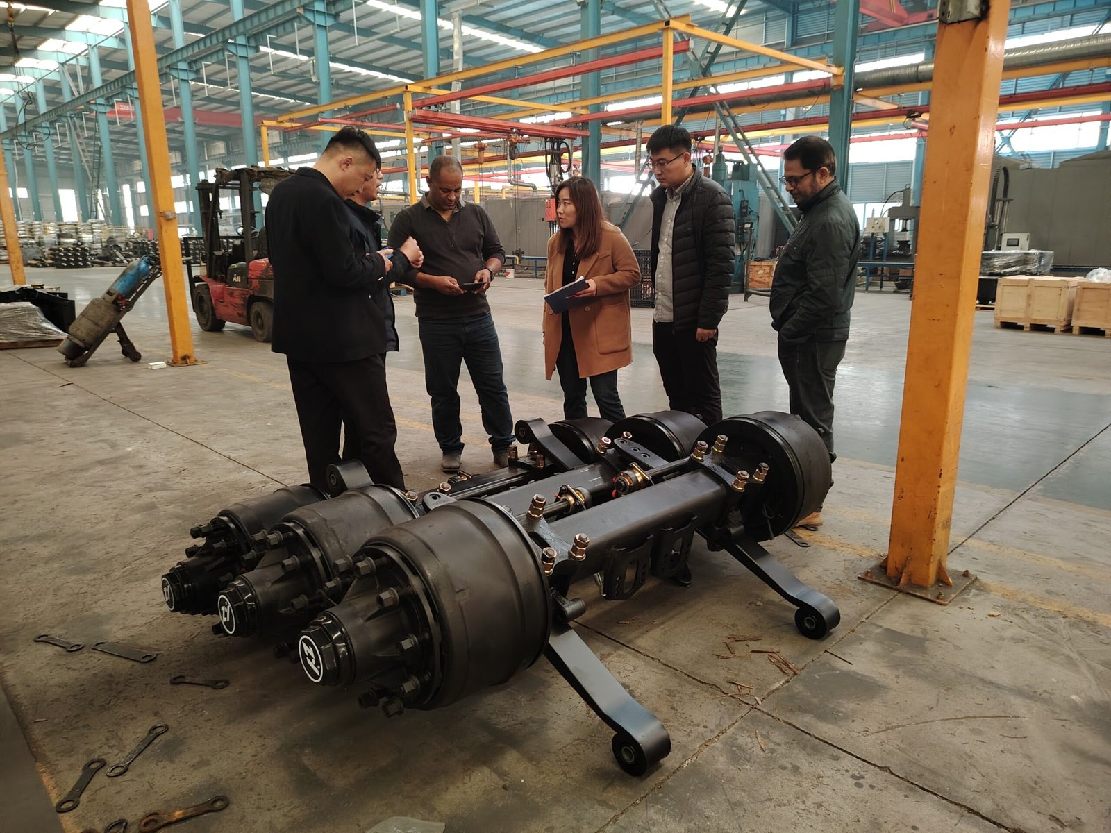
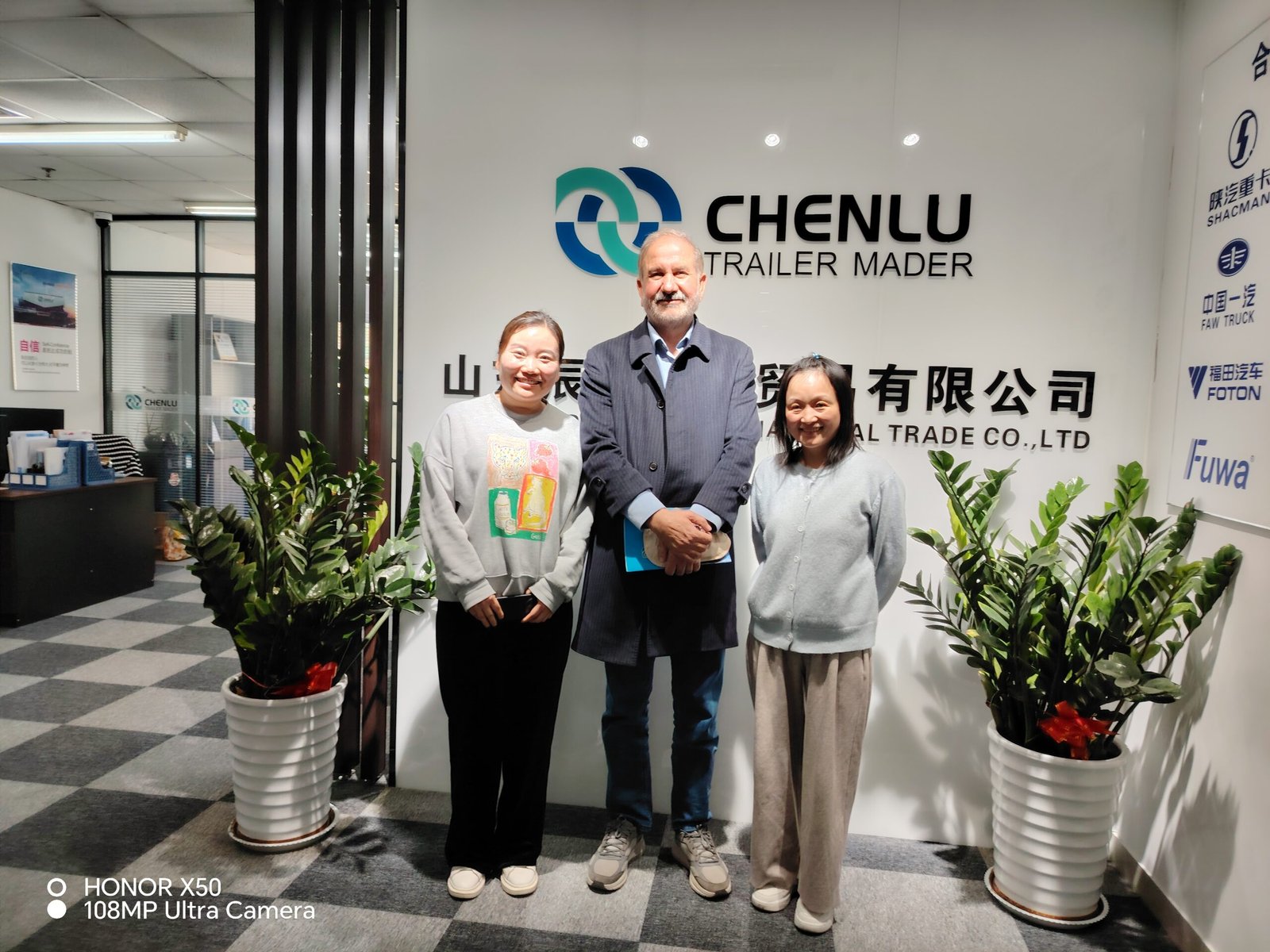
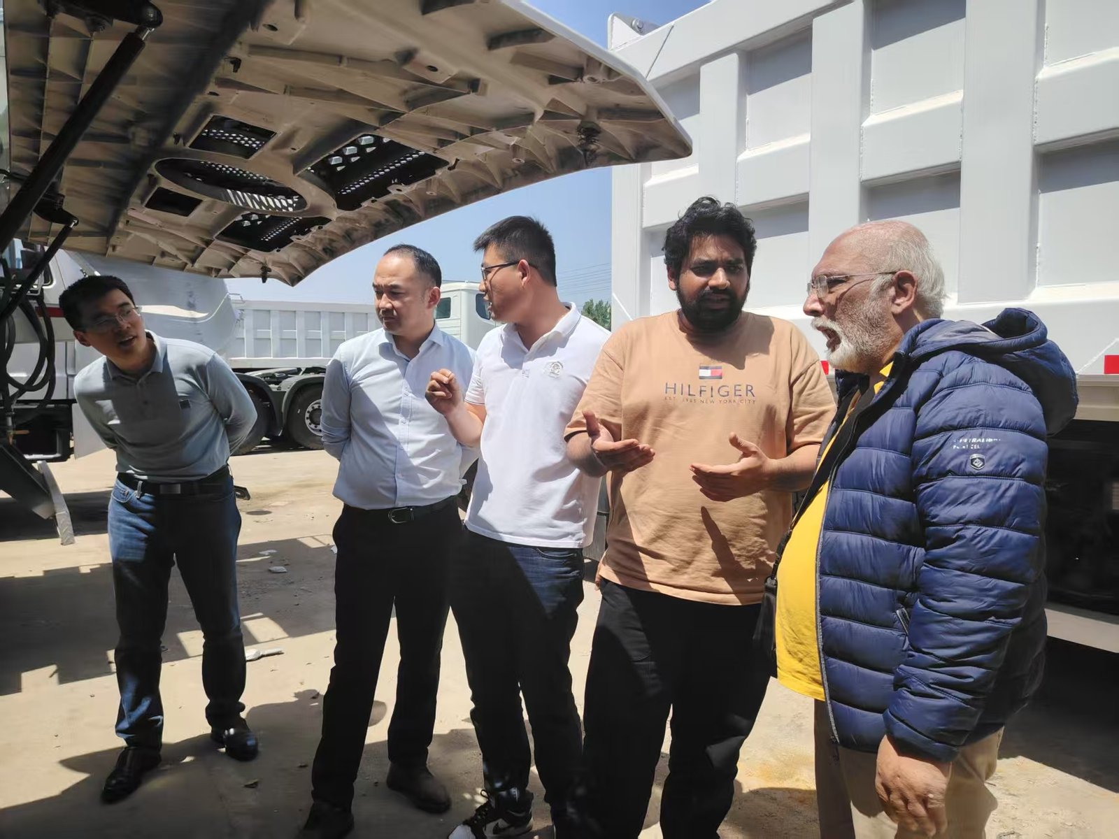
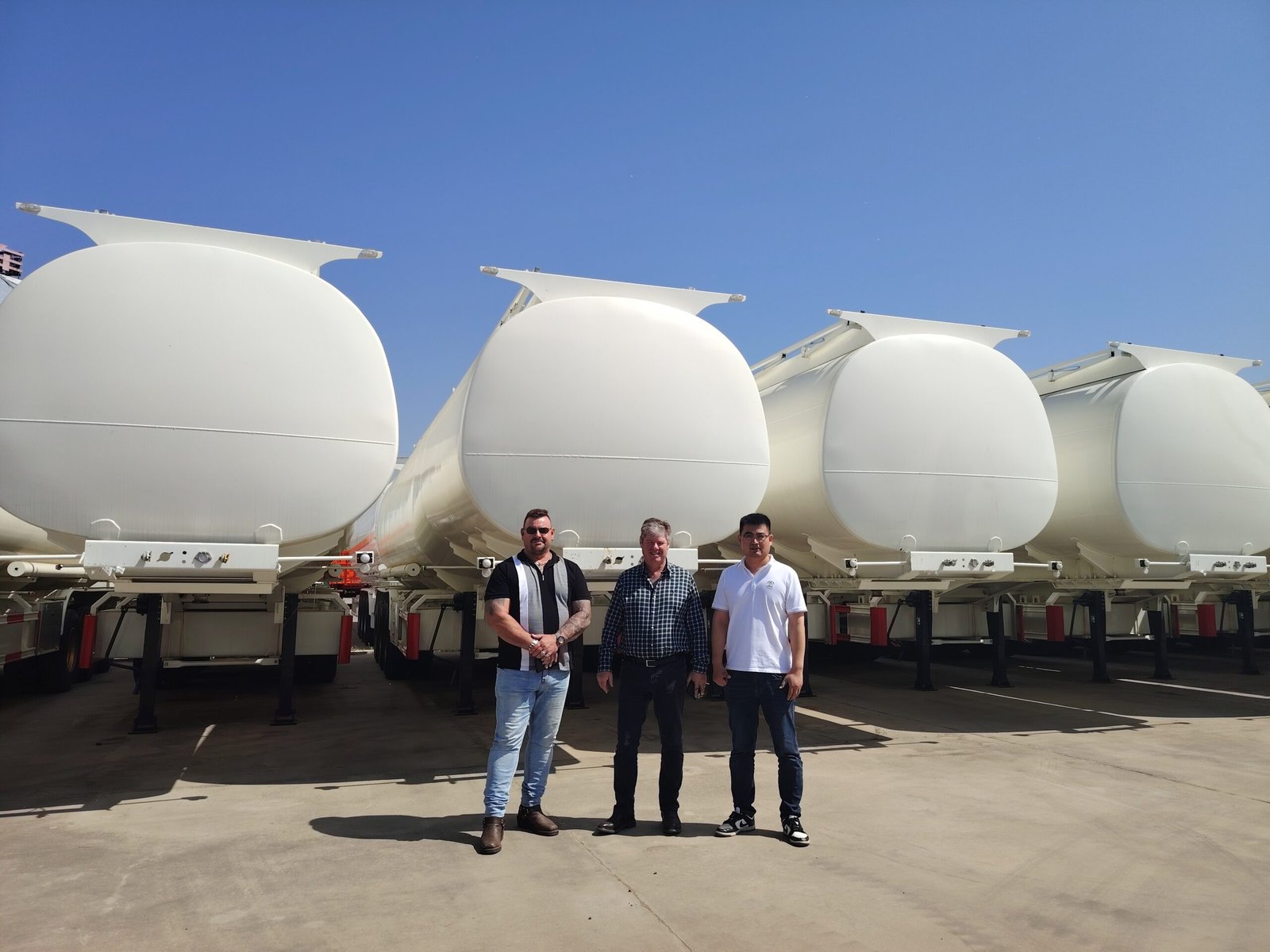
Meet Chenlu and Review the Manufacturing Process
Customer visits support direct communication between buyers, engineering teams and the manufacturing department before the final configuration is confirmed.

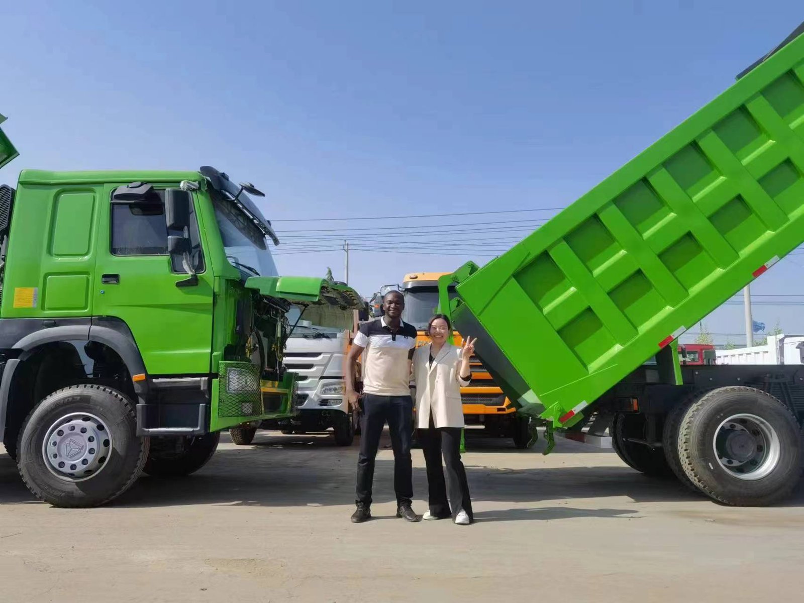

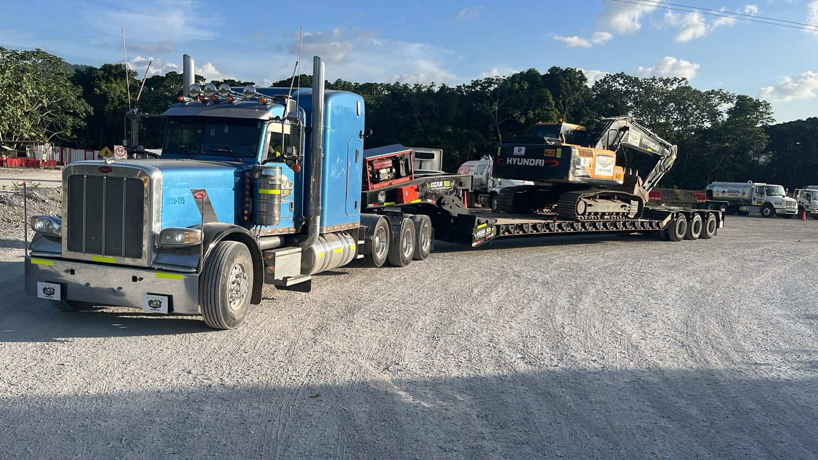
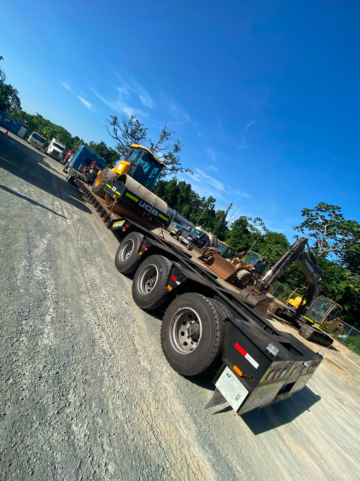
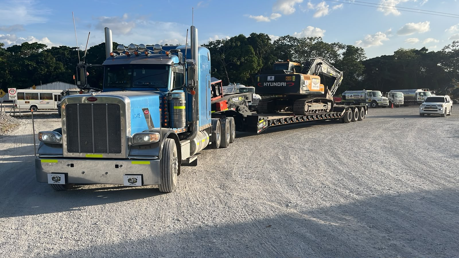
Follow the Project from Delivery to Customer Feedback
Use approved delivery photos, project records and customer comments to present the completed communication and delivery process.

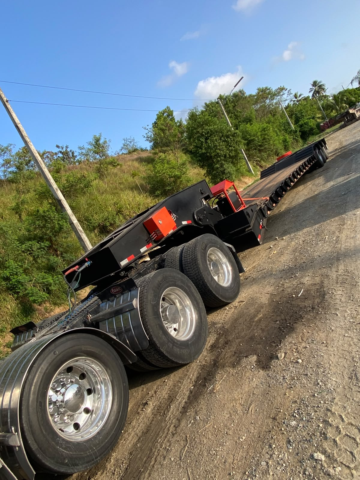
Publish the Original Customer Message with Permission
Add an approved customer comment, delivery record or project feedback here after the customer confirms the wording and image usage.
Approved delivery photo or project record.
Original customer message with permission.
Approved feedback about communication and support.
Related Products
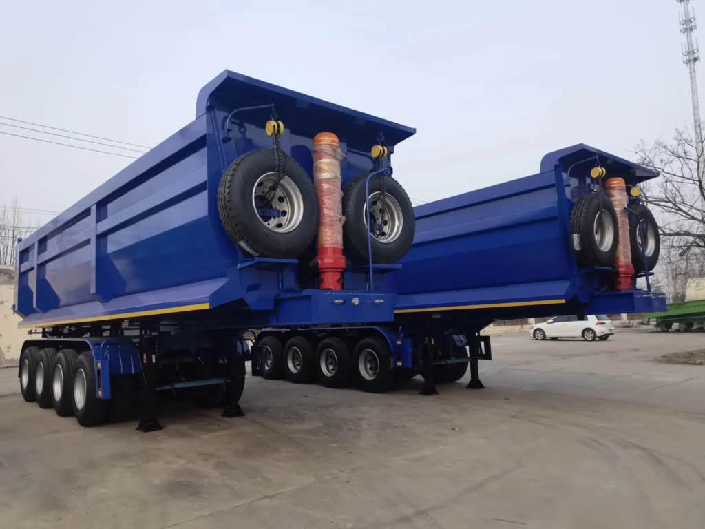
Tipper / Dump Trailer
100 Ton 4 Axle Rear Dump Semi Trailer with Air Suspension
View Product ↗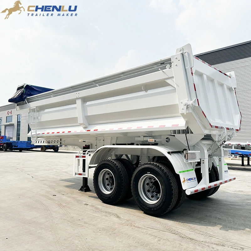
Tipper / Dump Trailer
2 Axle Rear Dump Semi Trailer
View Product ↗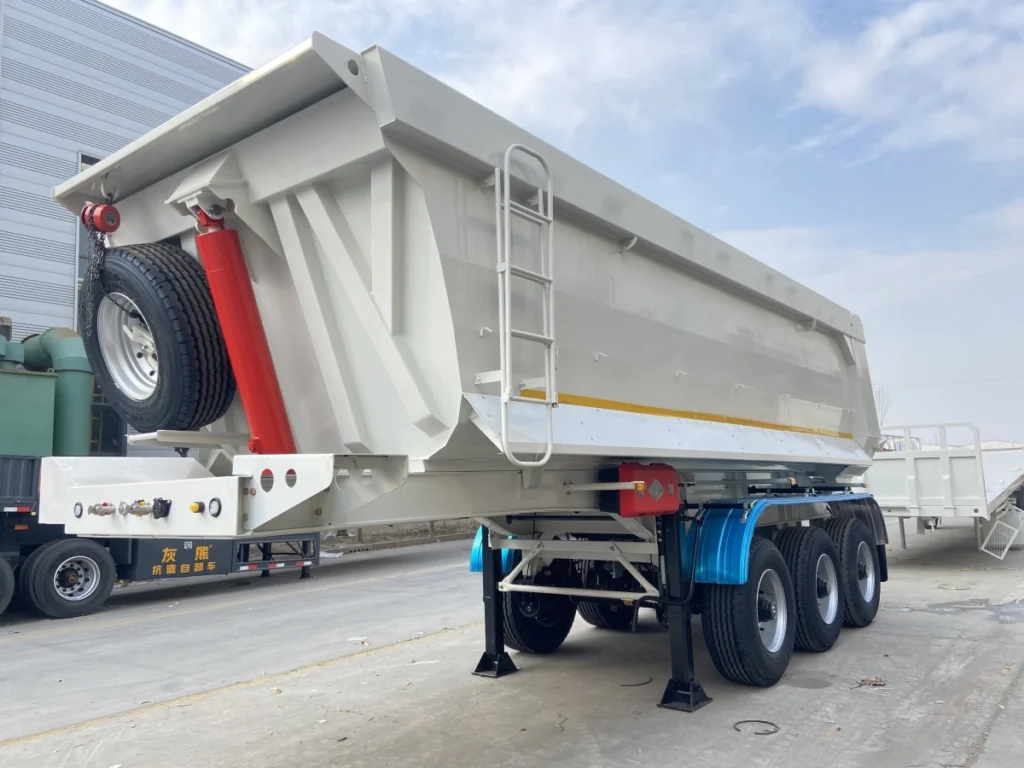
Tipper / Dump Trailer
3 Axle Rear Dump Semi Trailer for Saudi Arabia | CHENLU
View Product ↗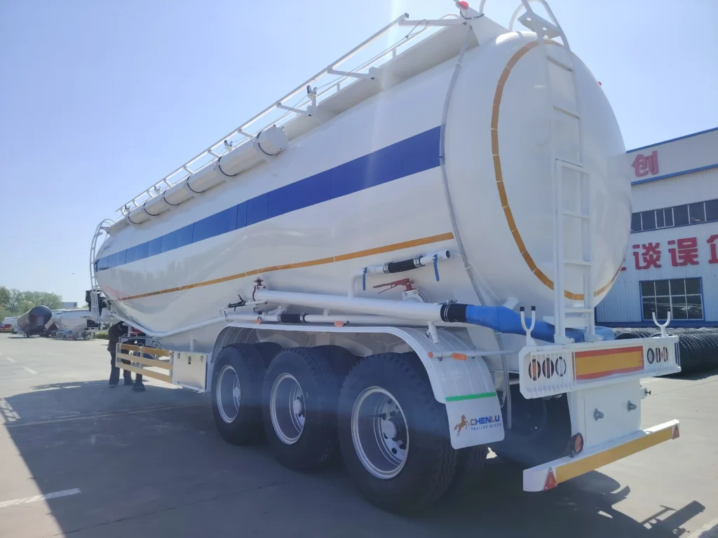
Bulk Cement Tanker
3-Axle Pneumatic Bulk Cement Tanker Semi-Trailer
View Product ↗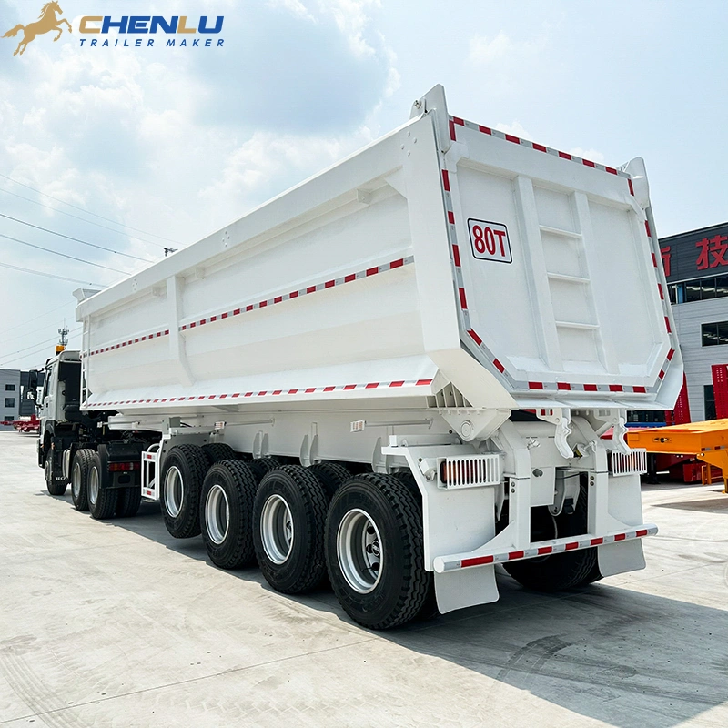
Tipper / Dump Trailer
4 Axle 80-Ton High-Side Rear Dump Semi Trailer
View Product ↗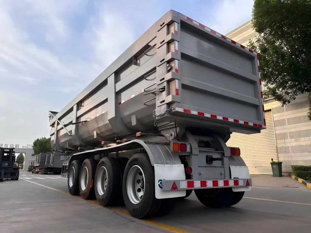
Tipper / Dump Trailer