
Cement Tanker Trailer Unloading: How Do You Match the Air Supply, Pipework and Receiving Silo?
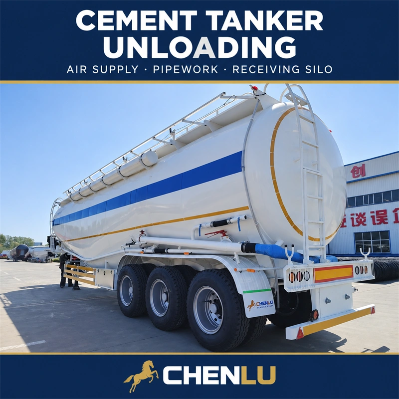
When choosing a CHENLU bulk cement tanker semi-trailer, tank volume and allowable payload affect the quantity carried per trip. The unloading configuration affects whether the cement can be conveyed smoothly into the customer's storage silo.
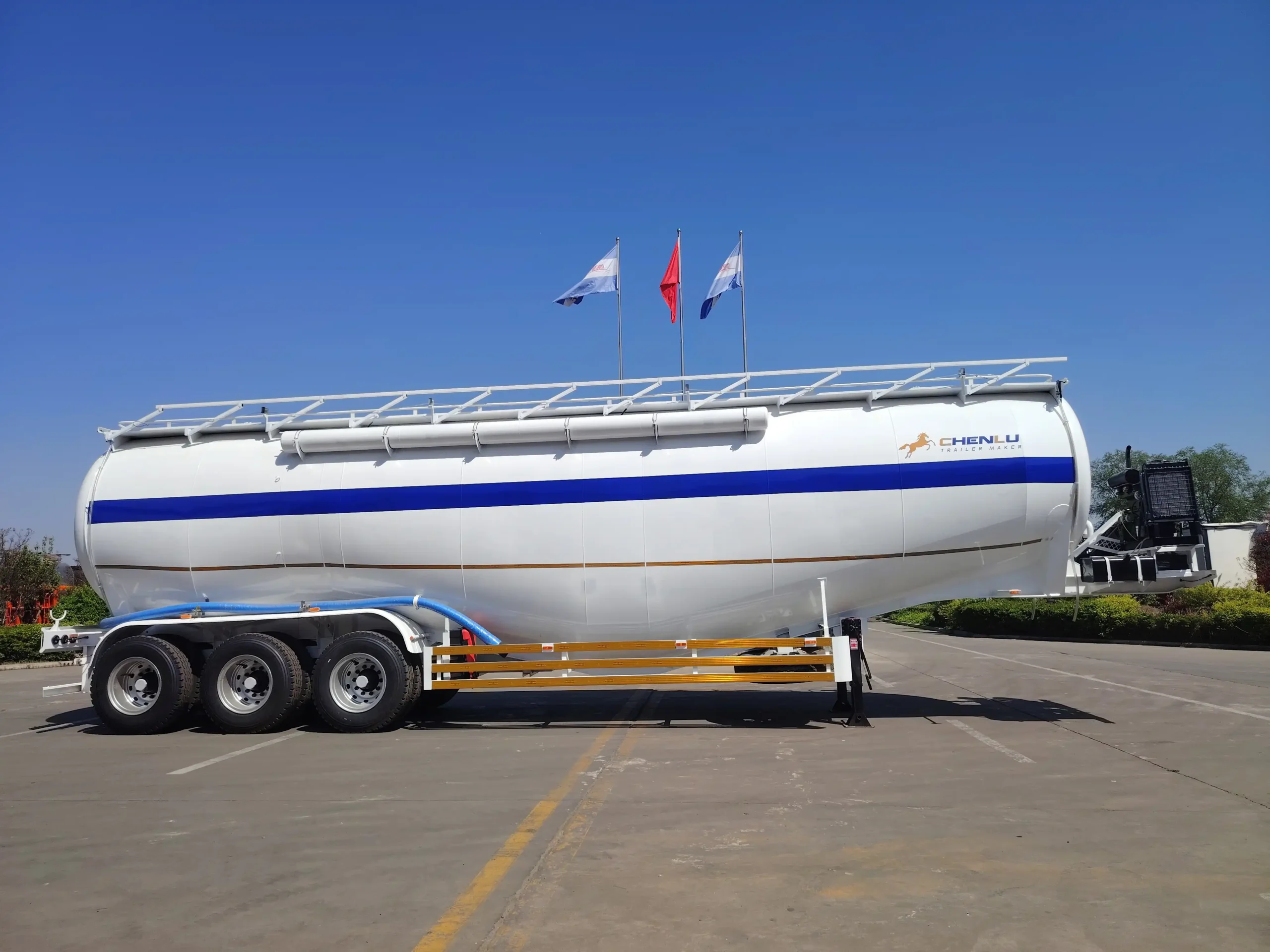
A bulk cement tanker semi-trailer carries dry cement in bulk. It can also carry other dry powders confirmed as suitable. The powder is loaded directly into a closed tank. The vehicle consists mainly of the tank, load-bearing chassis, air supply and unloading equipment. Tank volume, axle count and unloading configuration depend on the material, cargo weight and site conditions. CHENLU bulk cement tanker introduction
The tank holds the material, while the chassis and tractor coupling structure support and transfer the cargo load. Internal flow-guiding structures, the aeration system and the discharge outlet affect how powder leaves the tank. At the unloading site, a discharge hose connects the trailer to the receiving silo's feed pipe. Assessing unloading capability therefore requires checking the tank internals, air supply, conveying pipework and receiving equipment. CHENLU structure and configuration guide
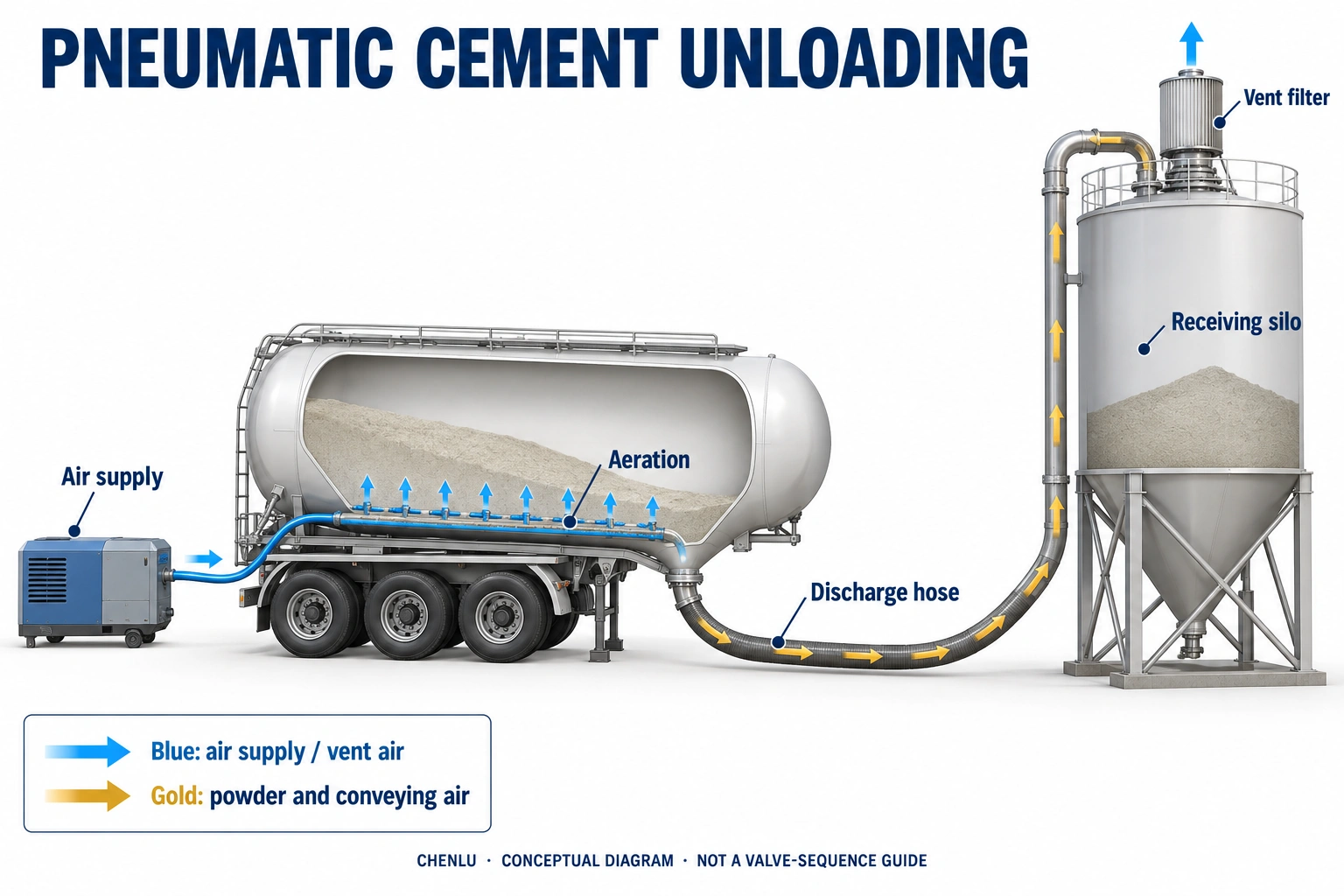
Cement tanker trailers generally use pneumatic unloading. During unloading, a compressor supplies air to the tank. The aeration system improves powder flow around the discharge area. Pressure differences and conveying air move cement through the outlet, discharge hose and receiving feed pipe into the silo. [1]
Air supply pressure and flow, pipe diameter, pipe length and bend layout all affect unloading performance. Conveying air entering the silo must also leave through the dust filtration system. The receiving silo's venting capacity therefore matters as well.
Match the system to the actual material and complete conveying route. Check the air supply's flow at the required operating pressure, the conveying conditions in the pipework, and the receiving silo's filling, filtered venting and pressure protection arrangements. These parts must work together under the site conditions. Compressor power, tank volume or coupling size alone cannot establish whether the complete system is suitable. [4], [6]
What Does Compressed Air Do During Unloading?
To understand the unloading system, first distinguish the different functions of compressed air.
The tank needs sufficient pressure to feed powder into the discharge pipework. The aeration system needs air to improve powder flow around the discharge area. Airflow in the conveying line then keeps the powder moving. These functions are connected, but raising tank pressure does not automatically unload cement faster. [7]
Air pressure and airflow are different measurements. Pressure is needed to overcome conveying resistance. Sufficient airflow is needed for aeration and transport. With insufficient airflow, a high pressure reading does not prove that conveying is normal. A restriction can also cause pressure to rise while material flow becomes poor.
Air branches, aeration equipment and control arrangements vary between tanker models. Some use separate top air, aeration air and conveying-air injection. Others use different combinations when handling cement. These functions can be explained as general principles, but valve sequences, adjustments and operating pressures must follow the manual for the specific model. [2]
Material condition also matters. Different powders respond differently to aeration and conveying. Moisture, lumps or changes in cement flow behaviour can affect how it enters the pipework. Configurations and unloading performance established for suitable dry cement cannot be applied directly to material in a substantially different condition. [1]
Select the Air Supply for the Actual Operating Conditions
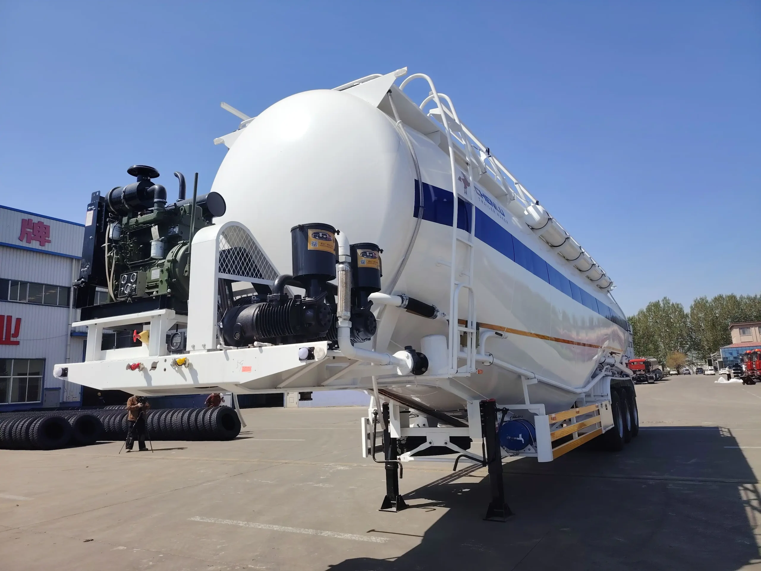
Compressed air can come from a tractor-PTO-driven unit, an independently powered unit or a fixed supply at the site. These choices determine the power source and how the trailer works with the site. Air supply performance must still be checked against the unloading requirements. [1]
When comparing compressors, do not consider only maximum pressure, rated power or model size. Check the airflow available at the expected operating pressure and whether it suits the material and complete route. Gardner Denver's dry bulk guidance identifies material properties, conveying diameter, distance and vertical lift as factors in pressure and airflow requirements. [4]
Airflow ratings must use comparable reference conditions. Free-air delivery, flow at standard conditions and actual volumetric flow in the working pipe may use different pressure and temperature references. Two ratings expressed in m³/min are not necessarily directly comparable. First confirm what each figure represents and its operating conditions.
For tractor-PTO drive, check the speed and power match between the tractor, PTO and compressor. For an independently powered unit, consider the available fuel or electricity and the conditions for sustained unloading. These factors determine whether the unit can maintain the required air supply at the site.
When discussing the air supply configuration with CHENLU, provide the tractor model and PTO details, or technical data for the existing site supply. Whether an existing compressor can be retained depends on its airflow capability under the unloading conditions.
A larger compressor does not automatically mean faster unloading. The additional air must still pass through the conveying pipework and leave through the receiving silo. If the line or receiving equipment is already the limiting factor, increasing the air supply alone will not resolve the system mismatch.
Check the Pipework from the Trailer Outlet to the Silo Inlet
The unloading route includes the trailer's conveying pipework, the connecting hose and the receiving silo's fixed feed pipe. Checking hose length alone can overlook the downstream section that affects conveying.
Establish the complete route: where the trailer parks, how the hose connects, the fixed pipe length, the vertical lift, the number of bends, and any reductions or other changes in cross-section. Silo height and actual conveying pipe length are different measurements. One cannot replace the other.
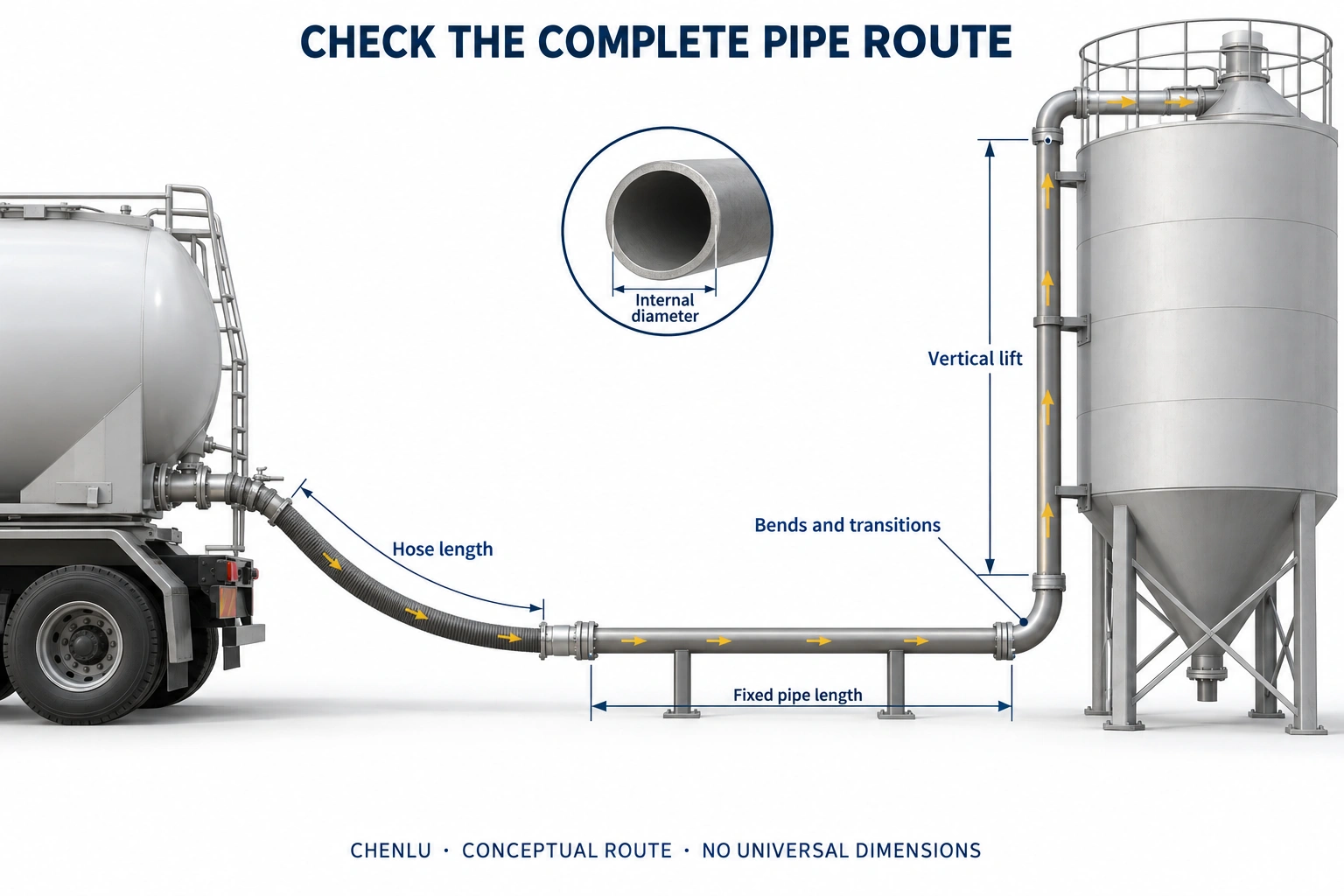
Powder and air must overcome friction along the pipe and resistance at fittings. Upward conveying also lifts the material. The same tanker can therefore have different unloading times at different receiving sites, even with similar loads. [7]
A larger pipe diameter is not always better. At a given point in the line, a larger cross-sectional area lowers average air velocity for the same actual volumetric airflow. Whether the larger diameter helps depends on airflow, the material's conveying behaviour and the full route. If airflow cannot maintain stable conveying, powder may accumulate in the line. A smaller diameter may increase resistance, so reducing pipe size is not a universal solution either. [3]
Check the effective internal diameter of the pipe and hose, rather than the nominal coupling size alone. Include bend positions, hose curvature and cross-section changes in the assessment. If the trailer serves several sites, record each route separately before defining the operating conditions the configuration needs to cover.
The Receiving Silo Must Hold the Cement and Vent the Air
Two conditions need separate checks: whether the silo has enough permitted receiving capacity for the load, and whether its venting system can handle the air entering with the material.
Conveying air must leave the silo after the cement enters. The roof-mounted vent filter separates dust from the airflow and lets air pass through the filter media. Filter capacity, media condition and the cleaning system all affect this process. [5]
Having space in the silo does not establish that unloading conditions are suitable. Restricted filtered venting can still cause silo pressure to rise. A conventional cement storage silo's allowable pressure must not be inferred from the tanker's operating pressure. Check the design information for the silo and its associated equipment. [7]
The receiving silo's devices have different jobs:
| Device | Main function | What to check |
|---|---|---|
| Silo vent filter | Separate dust and release conveying air | Airflow capacity, pressure drop, filter media condition and cleaning requirements |
| High-level detection and alarm | Indicate that material is approaching the set level | Permitted receiving quantity, alarm position and allowance after feed stops |
| Silo pressure detection and alarm | Monitor abnormal silo pressure | Basis for the settings and the required response |
| Pressure relief device | Release excess pressure under specified conditions | Opening conditions, relief capacity and maintenance condition |
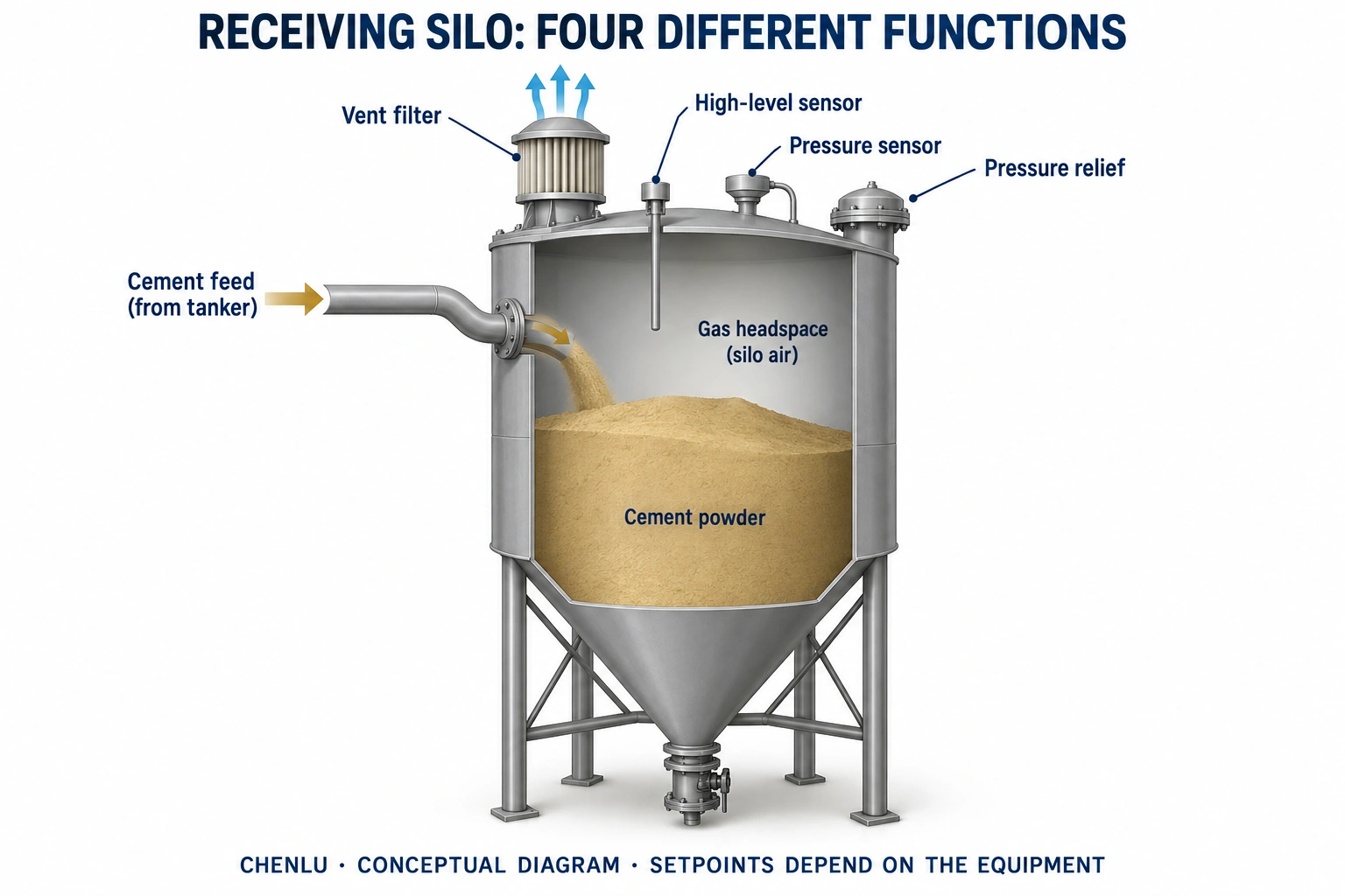
These functions cannot replace one another. A high-level alarm cannot establish whether a filter is blocked. A pressure alarm cannot replace level control. The pressure relief device should not serve as the routine air outlet during normal unloading. [6]
The receiving equipment must also accommodate the final stage of unloading. As the powder content in the line falls, airflow entering the silo may change. Uncontrolled release of residual compressed air from the tanker can also create a large short-term venting demand. Do not assess the receiving equipment only from average conditions during steady conveying. Follow the specific tanker manual and site procedures for the final unloading stage and residual pressure handling. [3]
How Do You Confirm the Unloading Configuration with CHENLU Before Ordering?
When sending CHENLU the planned cargo weight and cement type, include a simple drawing of the receiving site's feed pipework. Mark the parking position, coupling type, pipe internal diameter, hose length, fixed pipe route, vertical lift and bend positions. This allows the trailer outlet and site pipework to be checked together.
Provide air supply information as well. For tractor-PTO drive, supply tractor and PTO details. For a site compressor, provide airflow data at the relevant operating pressure. Assess whether existing equipment is suitable using these conditions.
The receiving site needs to provide the silo's permitted receiving quantity, filter information, cleaning requirements and pressure limits. Identify trailer configuration changes separately from site maintenance or modifications. For example, restricted silo-filter venting requires checking the receiving equipment. Replacing the vehicle's compressor alone will not address it.
If the same trailer delivers to several sites, list the main differences in pipework and couplings. Changes in hose length, vertical lift or receiving arrangements may also change the previously established unloading conditions.
Record the agreed air supply, discharge outlet and connection arrangement in the quotation and vehicle drawings. This ties tank capacity and the onboard unloading equipment to the receiving site conditions. See the CHENLU bulk cement tanker trailer page for models and configuration information.
Frequently Asked Questions (FAQ)
Can an Existing Site Compressor Replace the Onboard Air Supply?
It can be considered, but check whether the site supply meets the tanker's unloading requirements.
Some site compressed-air systems mainly serve instruments, valves or filter cleaning. They may not provide the sustained airflow needed for powder conveying. Confirm available pressure, airflow and its reference conditions, air quality and connections. Account for other equipment using air at the same time. The tanker also needs connections and a system configuration suitable for an external supply. [1]
Can Couplings Be Connected Directly If Their Nominal Sizes Match?
Nominal size alone is not enough.
Check coupling type, mating dimensions, seals and locking arrangements. Also check the hose assembly's pressure rating, temperature range and condition. Connection compatibility and operating conditions are separate checks. Couplings that fit together do not establish that the complete unloading system is matched. [6]
Why Are Unloading Times for Different Configurations Not Directly Comparable?
First check whether the time boundaries and unloading conditions are the same.
Some figures cover only the main conveying stage. Others include hose connection, establishing operating conditions, the final unloading stage, the specified pressure handling and disconnection. Cargo weight, material condition, pipe route, air supply and receiving equipment also affect the comparison. When agreeing performance requirements, record these conditions and the method for assessing allowable residue.
Can the Same Cement Tanker Trailer Switch Directly to Another Powder?
Being a powder is not enough to establish that the same configuration is suitable.
Different materials may behave differently during aeration and conveying. Recheck material properties, tank aeration equipment, the air supply and conveying conditions. Confirm tank and pipework cleaning requirements to prevent residue affecting the next load. Suitable materials must be confirmed from the specific model information and by the supplier and buyer. [1]
About this article
This article discusses matching a tanker unloading system to a storage silo when handling bulk cement suitable for pneumatic conveying. External sources explain general engineering principles. The configuration of a specific CHENLU model is governed by the confirmed quotation and drawings. Operating requirements follow the relevant model manual and site procedures. Management requirements in the UK guidance are not presented as universal requirements for other markets.
References
- Convair: Tanker Owner's Manual The cover of the reviewed file identifies Version 001. Used to explain aeration equipment, powder conveying paths, air supply options and material differences.
- Convair: FFB Tanker Manual Used to distinguish tank pressurisation, aeration air and conveying-air injection, and to explain why the air arrangement depends on the model.
- Convair: Unloading Instructions v002 Used to explain insufficient conveying airflow, restricted receiving-side venting and issues during the final unloading stage.
- Gardner Denver: Dry Bulk Pneumatic Conveying Guidance Used to explain how air supply selection relates to material, pipe diameter, conveying distance and vertical lift.
- Polimak: Cement Silo Filter Guidance Used to explain filtered release of conveying air and filter cleaning.
- MPA: Guidance to Prevent Over-Pressurisation of Storage Silos Used to distinguish filtered venting, level detection and pressure protection, and pressures in the tanker, pipework and receiving silo.
- UK Defra: Process Guidance Note 3/01(12), September 2012 Used to support explanations of compressed-air functions, conveying resistance and receiving silo venting conditions.
MORE FROM OUR NEWSROOM
Related News
Container Chassis vs Flatbed: Choosing for Your Loads | CHENLU
Compare container chassis an…
Read News ↗
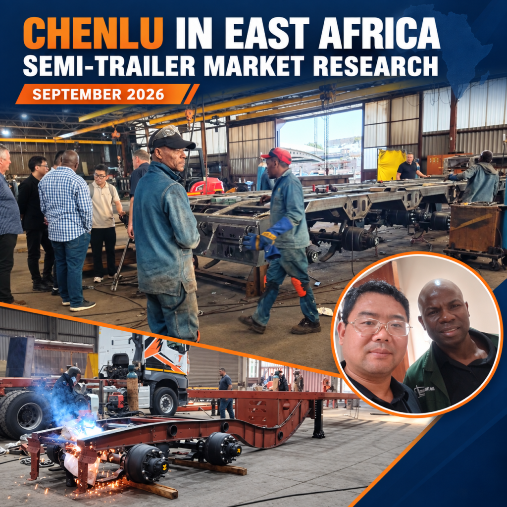
CHENLU Studies East Africa’s Semi-Trailer Market and Manufacturing
From September 10–22, 2026, …
Read News ↗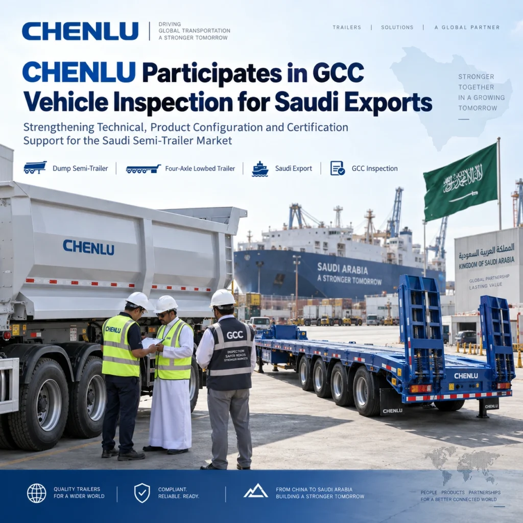
CHENLU Participates in GCC Vehicle Inspection for Saudi Arabia Semi-Trailer Export Projects
CHENLU joined a technical br…
Read News ↗